Yes I tried the Kingbright LEDs on 3 different multimeters. The meters were cheap ($40), cheaper ($15), and cheapest ($6). Besides giving the expected diode reading on the DMM display, both LEDs lit up on all three meters. The green LED glowed green and the red LED glowed red. Thus the DMM reminds you which end is cathode and which end is anode, and it is an easy way to verify that the water-clear-plastic LED in your hand, glows green. So you should solder it into the green LED position: D4, Windings In Phase.Just use your digital multimeter at diode function and done. See the attached pic.
Why you are searching for a tree and lose the forest?
Just use your digital multimeter at diode function and done. See the attached pic.
I'm aware of the fact that most LEDs will light up on a DMM's diode test, but that was not the point. The point was that once the uneven length leads of new LEDs are clipped to the right length, you still have the ability to determine anode and cathode without having to resort to a multimeter.
Use the Mains Bulb Tester you have lying on the shelf.Hey this is very useful - I have long forgotten custom toroids with multiple secondaries that I can never remember how to wire up for series/parallel as the wires are all the same color! ...............
Use it to check the wiring of any/every mains transformer, especially those that don't have wiring instructions.
The cup structure/reflector is nearly always the -ve side.Well, there is another way if the LED is clear or semi-clear. There's a cup-like structure inside the LED. I guess it's what holds the junction as the light is emitted from it.
With normal LEDs, I have always seen that this structure is connected to the kathode and it clearly takes up more space inside the LED than the anode.
An externally hosted image should be here but it was not working when we last tested it.An externally hosted image should be here but it was not working when we last tested it.
I too gave advice on this in this Forum, until a Member said I was wrong.
I went to my stock of single colour LEDs, and compared short lead, and flat and cup reflector and all except one were consistent. The Bar on the schematic symbol, and the Cup and the Flat and the Short lead are the Cathode side and go to the -ve side.
BTW, you can see the tiny wire from one lead looping into the centre of the reflector. Maybe like the "cat's whisker" of the early diodes/transistors.
BUT !!!!! one diode type had the cup reflector on the anode side.
I don't understand why, or how, this discrepancy can occur.
But the accusation was right. I was wrong. Not all cathodes are indicated by the cup reflector.
This makes it difficult to identify 3mm LEDs (no flat on the side) that have been trimmed. One has to polarity test to check for correct orientation.
Last edited:
Use the Mains Bulb Tester you have lying on the shelf.
Unfortunately a Mains Bulb Tester won't find every kind of transformer wiring error. I'll let theoretically-inclined readers state a single-sentence rule which describes the kinds of errors it won't find; instead I'll merely exhibit one example (attached).
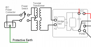
This is the power supply wiring diagram from the Akitika GT-101 audio power amplifier, when used with 115VAC mains such as in USA. The transformer has two primaries, each 115VAC. It also has two secondaries, each 35VAC. The goal is to deliver 70VAC to the bridge rectifier.
For 115VAC operation, the primaries should be wired in parallel and the secondaries should be wired in series.
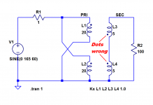
However, if you accidentally connect the secondaries incorrectly and test it with your mains bulb tester, you get no indication that anything is wrong. Try it in real life. Or try it in simulation. The mains bulb detector has no idea that the secondary windings are out of phase; it doesn't tell you the dots are wrong.
(if you try it in simulation, remember to install a teeny bit of series resistance in each winding; I used 100 micro-ohms)
Attachments
Last edited:
One can wire the dual primaries out of phase and the Bulb turns ON.
Or one can wire the secondaries out of phase and shorted and the Bulb turns ON.
Or one can wire both the multiple primaries and the multiple secondaries out of pahse and the Bub turns ON.
All transformer wiring errors are protected from damaging the transformer using a correctly wired Mains Bulb Tester.
When the secondaries are in series and out of phase, no current flows. Try it.Or one can wire the secondaries out of phase and shorted and the Bulb turns ON.
BTW, your right hand diagram will not damage the transformer.
But once you measure the output voltage you will find near zero volts across the 100r resistor. The resistor will stay cold.
Ah ! one thinks and rewires either one of the primaries or one of the secondaries.
Powering ON this time either brings on the Bulb or gives one the expected 100r voltage. i.e. it gets hot.
It was because of this ambiguity in wiring dual primaries/secondaries that I asked about a "safe" way to check the transformer wiring, since it seemed that guessing and getting it wrong, usually resulted in blowing yet another fuse @ 13p each.
The Forum gave me no useful answers.
It was some time later I discovered that Valve guys used a Mains Bulb Tester to check old equipment before direct on line powering and I realised this one piece of test equipment solved the risk of damage if wiring the mains transformer incorrectly.
The Mains Bulb Tester seems to be fool proof. It prevents catastrophic damage to transformers and PSUs.
It cannot be guaranteed to prevent damage to small components in an incorrectly assembled amplifier/DAC/Pre-amp/Crossover.
But wiring a pair of diodes across the +ve & -ve supplies to Power Ground, at the LV circuit power inputs, does prevent damage due to applying reverse polarity to a small circuit and protects against a mis-wired rectifier that tries to apply the wrong voltages to the +, - & 0 power inputs.
Last edited:
To disambiguate the phase dots of series windings, you want someone to connect their transformer to a Mains Bulb Tester AND a load resistor AND a voltmeter? The signal generator + oscilloscope method (picture 1 of post#1) is simpler and far safer. So is the PhaseDots tester board.
Personally, I would rather test the transformer and find the correct phase dots beforehand. Then the transformer can be connected to the mains and to the remaining circuitry with confidence that the wiring is correct and no damage will occur, catastrophic or otherwise. I also prefer to test the transformer in a safe, low voltage arrangement that has no live mains wires. Either the signal generator + scope method or the PhaseDots tester + 9V battery method. Why horse around with a live-mains test setup if other options are available and very cheap?
For those who don't own a signal generator and oscilloscope, building a PhaseDots tester on a little piece of VeroBoard (StripBoard in USA) is quick, simple, and inexpensive: 2 CMOS logic ICs, 1 NE555 timer IC, and 2 LED drivers. Parts cost was USD 7.00 per PhaseDots board when I made my buy from MouserUSA back in April. Since there's nothing even remotely exotic on the BOM, you could buy everything from a discount far-East supplier like Tayda or Futurlec, and pay even less.
No.To disambiguate the phase dots of series windings, you want someone to connect their transformer to a Mains Bulb Tester AND a load resistor AND a voltmeter?
I have posted many times.
Connect the transformer via the Mains Bulb Tester (MBT) and Power ON.
Does the bulb light?
Power OFF.
Sort the error, or proceed.
Add on the rectifier
Does the Bulb light?
Power Off.
Sort the error, or proceed.
Add on a smoothing capacitor.
Does the Bulb Light?
Power OFF.
do it in stages.
Check each modification, using the Mains Bulb tester.
I have not commented on whether your new testing is good, or great, or safe, or unsafe.The signal generator + oscilloscope method (picture 1 of post#1) is simpler and far safer. So is the PhaseDots tester board.
I have added my comment about using the MBT
The Mains Bulb Tester is simpler and cheaper and can be used for many Mains Power testing.Personally, I would rather test the transformer and find the correct phase dots beforehand. Then the transformer can be connected to the mains and to the remaining circuitry with confidence that the wiring is correct and no damage will occur, catastrophic or otherwise. I also prefer to test the transformer in a safe, low voltage arrangement that has no live mains wires. Either the signal generator + scope method or the PhaseDots tester + 9V battery method. Why horse around with a live-mains test setup if other options are available and very cheap?
For those who don't own a signal generator and oscilloscope, building a PhaseDots tester on a little piece of VeroBoard (StripBoard in USA) is quick, simple, and inexpensive: 2 CMOS logic ICs, 1 NE555 timer IC, and 2 LED drivers. Parts cost was USD 7.00 per PhaseDots board when I made my buy from MouserUSA back in April. Since there's nothing even remotely exotic on the BOM, you could buy everything from a discount far-East supplier like Tayda or Futurlec, and pay even less.
(picture 1 of post#1) is simpler and far safer. So is the PhaseDots tester board.
So this song still goes in the same tune.
Since transformers does not have polarity, and input phase can be connected when ever I like so, I do become automatically aware of where is my input phase = my first PhaseDot.
My second it can be found by a simple two pole phase rotation gadget which the specific UT15C, this it can additionally perform, voltage measurement, continuity test, and a coffee if you need one.
Unfortunately you must also have a source of AC waveforms, such as signal generator or the AC mains, since the UT15C is unable to provide a stimulus waveform. Maybe you will want to build a battery powered NE555 signal generator using $2.00 worth of parts from your junkbox -- since a battery powered device is less dangerous than the AC mains.My second dot can be found by a simple two pole phase rotation gadget which the specific UT15C, this it can additionally perform, voltage measurement, continuity test, and a coffee if you need one.
I don't know about Greece but in the USA an UT15C costs $25.00 (here are some online prices). This is far more expensive than a $13.00 PCB + kit of parts.
So this song still goes in the same tune.
Since transformers does not have polarity,
Are you sure about that? Try connecting two primaries in anti-series and come back to tell the result: you won't have enough time to connect your UT15 marvel anywhere
What you don't seem to realize is that the UT15 relies on a crummy "contact electrode (8)" as a phase reference, ie you yourself are part of the test setup, but that presupposes you are earthed, and the mains delivery conforms to a specific standard, typically TNx.and input phase can be connected when ever I like so, I do become automatically aware of where is my input phase = my first PhaseDot.
My second it can be found by a simple two pole phase rotation gadget which the specific UT15C, this it can additionally perform,
In regions of Canada for example, this wouldn't work. Even in a TNx environment, this will not necessarily work, because your body might be more tightly coupled to one phase than the earth (remedy: stay bare foot in a pool of salt-water during the test)
What you don't seem to realize is that the UT15 relies on a crummy "contact electrode (8)" as a phase reference
I have no idea of how it works, for the same reason that I do not perform a chemical analysis to water melons before eating them.
But if industry it does trust this solution in applications with electric motors which their pricing vary up to several thousands dollars, then this it is good for me.
This UT15C as product design is distributed by at least 15 known brands of branded and OEM test and measurement tools.
Unfortunately you must also have a source of AC waveforms, such as signal generator or the AC mains, since the UT15C is unable to provide a stimulus waveform. Maybe you will want to build a battery powered NE555 signal generator using $2.00 worth of parts from your junkbox -- since a battery powered device is less dangerous than the AC mains.
I don't know about Greece but in the USA an UT15C costs $25.00 (here are some online prices). This is far more expensive than a $13.00 PCB + kit of parts.
Hey Mark if you prefer to pretend the electronics repair man with an empty tool box, this is your choice mate.
What the rest of the world will do, it is his own problem.
If you discover how much this tester is priced as FLUKE tool, you will lose your hairs.
The PhaseDots Bill Of Materials specifies that C8 should be a "low leakage electrolytic." People buying their own parts to solder into a PCB have asked: (i) why?, and (ii) how low is low?
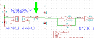
Why? If C8 leaks, the leakage current will disturb the input bias of the first stage of amplification (these stages are CMOS inverters operated in their linear region). Suppose we're measuring a transformer with a voltage stepdown ratio of 230-to-3. Then the 8V square wave in the primary becomes a 100mV square wave on the secondary, at node TINY. If C8 leaks 10uA then node TINY is offset by (10uA x 7.5K) = 75 mV, and the input signal is almost obliterated. {obviously this analysis has been oversimplified for brevity}
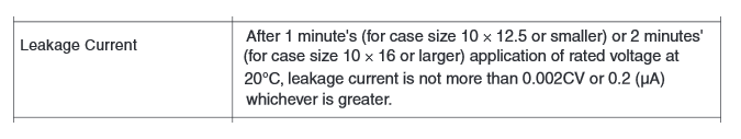
How low? I'm shipping a 10uF, 25V capacitor from the Nichicon KL series, in the Phase Dots kits. This is probably excessive overkill, but my feeling is, it only cost twenty cents so why not use parts that are too good instead of not good enough? The leakage spec from the Nichicon KL datasheet (link here) is shown below.
_
Why? If C8 leaks, the leakage current will disturb the input bias of the first stage of amplification (these stages are CMOS inverters operated in their linear region). Suppose we're measuring a transformer with a voltage stepdown ratio of 230-to-3. Then the 8V square wave in the primary becomes a 100mV square wave on the secondary, at node TINY. If C8 leaks 10uA then node TINY is offset by (10uA x 7.5K) = 75 mV, and the input signal is almost obliterated. {obviously this analysis has been oversimplified for brevity}
How low? I'm shipping a 10uF, 25V capacitor from the Nichicon KL series, in the Phase Dots kits. This is probably excessive overkill, but my feeling is, it only cost twenty cents so why not use parts that are too good instead of not good enough? The leakage spec from the Nichicon KL datasheet (link here) is shown below.
_
Attachments
Last edited:
You must be joking or you simply don't understand the OP or subsequent posts......Now my opinion is that this PhaseDots / phase shift detection, does no seems crucial.
Especially when the output gets converted to DC.....
Take any dual primary or multiple winding (not multi-tapped) secondary trafo and try your opinion out by reversing the leads of one winding that is either in a parallel or series arrangement. I suggest you don't start with the primary windings, as it could destroy some device in the powered circuit.
https://www.google.com.au/url?sa=t&...=VLO7qHb6vj7uu1fWoPZGGQ&bvm=bv.96041959,d.dGc
Hammond Mfg. - Basic Transformer Hook Up Data
From a safety point of view, there is no need to expose people to mains voltages. I think any development that is powered and operates with low voltage and current, is a much better plan if it avoids safety risks with unknown voltages and testing arrangements. Avoiding collateral damage and replacements is not such a bad idea either.
Kudos to Mark J. Thanks for sharing your design and kit offers
")
Last edited:
Mark,
thanks for that link to the low leakage electrolytic.
leakage < 0.002CV is roughly 10times better than ordinary electrolytics.
I find that reforming a good but ordinary electrolytic can improve the leakage from a specified 0.03CV to between 100times better to 500times better.
After reforming and then exposing them to a low bias voltage will allow them to degrade slowly back to their leaky state. Shortly after a double reform the leakage ~0.0003CV to ~0.00006CV
Tantalum is slightly better.
BTW, I need to use reforming resistors of ~50k to be able to measure the leakage. And leaving a fully charged newly reformed cap on the bench for a month loses <30% of it's charge.
I wonder how good the Nichicon KL is after reforming and how well it retains the super low leakage when stored at low voltage?
Sounds like an experiment you could try in your lab!I wonder how good the Nichicon KL is after reforming and how well it retains the super low leakage when stored at low voltage?
Maybe you'll also try inserting a shorting bar into the "Winding_2" connector of your PhaseDots board, thereby establishing a bias of (Vcc/2) = 4.5 volts across the low leakage capacitor C8. Then make a plot of (C8 leakage) versus (number of seconds at 4.5V dc bias). You could also experiment with plugging various resistor values into the Winding_2 connector; after all, a shorting bar is nothing more than a zero ohm resistor. Maybe a one megohm resistor would give amusing and instructive behaviors.
Perhaps you will be able to gather enough data to confidently suggest a lab protocol that minimizes capacitor leakage. Maybe something like (a) insert a resistor across Winding_2 connector whose resistance is less than 220 ohms; (b) turn on PhaseDots box for at least 15 seconds; (c) remove resistor and use box normally; (d) repeat (a)-(c) after each 50 hours of continuous PhaseDots use.
But remember - leakage is only significant when testing gigantically huge transformer stepdown ratios. Specifically, single 230V primaries (not dual primary 115V+115V) and super low voltage secondaries. I expect this to be less than 0.1% of the total usage of PhaseDots boards.
- Home
- Amplifiers
- Power Supplies
- A little tester to determine transformer PhaseDots with no scope or signal generator