Sup Y'all, I am wondering what PSU oscillation looks like on an oscilloscope. Specifically I'm trying to learn what it looks like for a linear regulator (+/-15V) under load. Does anyone have any pics of their scope capturing PSU oscillation?
I have an analog scope. Will the oscillations always be steady enough to trigger?
If you have pics of other power supplies oscillating like unregulated power amp's supplies, please post them as well.
I have an analog scope. Will the oscillations always be steady enough to trigger?
If you have pics of other power supplies oscillating like unregulated power amp's supplies, please post them as well.
I have some nice captures made with an Agilent (now Keysight) DSO-X 3054A at work of an oscillating LM337.
The oscillations were caused by too low ESR of the capacitors on the output of the LM337. LDOs (like LM317/337s) don't like that.
These oscillatons were strong and pretty steady and any scope should trigger them without any problem. I'll post one capture soon.
Edit: unregulated PSU's don't oscillate as they don't have any feedback. Did you mean ripple voltage?
Last edited:
I am wondering what PSU oscillation looks like on an oscilloscope.
Specifically I'm trying to learn what it looks like for a linear regulator (+/-15V) under load.
If you use a large enough cap, there's no issue.
I'll post one capture soon.
unregulated PSU's don't oscillate as they don't have any feedback. Did you mean ripple voltage?
Awesome, thanks jitter. That is a serious scope you have there.
Thanks for pointing that out about the feedback causing oscillations, I didn't think of that. Nevermind on the pics of unregulated then.
Last edited:
Hi shredhead,
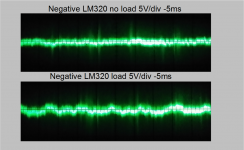
It looks like a higher frequency signal riding on the DC supply voltage, which may or may not be the correct level depending on the waveform. If the level of oscillation isn't high enough to trigger with, the trace will look fatter than normal. Noise can also make a trace fatter, but whichever the cause, this needs to be fixed.
Increasing supply capacitance has been in vogue for a few years now. Add that to fast diodes (now soft recovery diodes to fix that problem), and you set yourself up for problems. Notice that the "soft recovery diodes" came about after the dirty little secret came out that is reduced conduction angle and sharp current spikes. The real fix? Use the properly sized capacitor and normal diodes that will handle the current (+ peak current rating!).
It looks like a higher frequency signal riding on the DC supply voltage, which may or may not be the correct level depending on the waveform. If the level of oscillation isn't high enough to trigger with, the trace will look fatter than normal. Noise can also make a trace fatter, but whichever the cause, this needs to be fixed.
No, not true. Larger caps can have higher inductance and will always create a reduced conduction angle which in turn causes radiated noise and bigger current spikes. Sometimes you are better off with a 120 Hz ripple that can be cleaned much more easily than the mess caused by large capacitance (worse with fast diodes).If you use a large enough cap, there's no issue.
Increasing supply capacitance has been in vogue for a few years now. Add that to fast diodes (now soft recovery diodes to fix that problem), and you set yourself up for problems. Notice that the "soft recovery diodes" came about after the dirty little secret came out that is reduced conduction angle and sharp current spikes. The real fix? Use the properly sized capacitor and normal diodes that will handle the current (+ peak current rating!).
The real fix? Use the properly sized capacitor and normal diodes that will handle the current (+ peak current rating!).
Do you have any suggestions of what to look at to properly size PSU ripple caps, regulator output caps and local PCB decoupling caps for a project?
Is there a worst case scenario of capacitance for demanding source material multiplied by how many op amps you are powering kind of formula or something like that?
Does anyone have any pics of their scope capturing PSU oscillation?
I could find/make some, but that wouldn't help, quite the opposite in fact: parasitic oscillations can appear in so many shapes and guises that showing a few "typical" examples could in fact mislead you into thinking your circuit is OK, when in fact it isn't.
No, but that isn't important: you are expecting to see pure DC. If you chose AC coupling and maximum sensitivity, the trace should stay perfectly flat, without any thickening or any other artifact.I have an analog scope. Will the oscillations always be steady enough to trigger?
Sometimes, you will see a clear phenomenon, like sawtooth oscillation or similar, but very often it will be a blurred or thickened trace., because the oscillation is not coherent, or too weak, or too high in frequency to be displayable, but it doesn't actually matter: you just look for signs of presence.
With the max sensitivity, the oscilloscope might give some thickening of the trace due to internal noise.
To make sure the noise you see is actually caused by the PSU you examine, just remove the mains power leaving the rest unchanged: if the artifact disappears, you can be sure the PSU is the culprit.
Note that an analog scope is ideal for this kind of job, because you don't have to worry about the sample rate/vs horizontal settings, sync, etc: just connect the probe and see if there are any visible changes, that's all
@shredhead
Take an look on this very nice document:
http://cds.linear.com/docs/en/application-note/an104f.pdf
Document explain how to test your PSU for transient response which is crucial to get picture about control circuit (regulator + FB).
In many cases, wrongly implemented FB and it's compensation lead to poor phase margin which consequently lead to oscillations on regulator's output.
Read whole document with attention and you will get an picture what you need to do.
In addition to what Chris points out, you can hear oscillation with an inexpensive transistor radio, or the error amplifier will get hot and possibly fail.
With Walt Jung's regulators on Jan's original "Old Colony" boards and the ADA797 as error amplifier you could hear the signal in the a.m. band.
You can use Fred Dieckman's regulator tester to examine PSRR and Zout. If you can find Zout, you can find phase/gain relationship:
With Walt Jung's regulators on Jan's original "Old Colony" boards and the ADA797 as error amplifier you could hear the signal in the a.m. band.
You can use Fred Dieckman's regulator tester to examine PSRR and Zout. If you can find Zout, you can find phase/gain relationship:
hi,
Another good read and build to test snubbers and PS is here
http://www.diyaudio.com/forums/powe...sformer-snubber-using-quasimodo-test-jig.html
NS
Another good read and build to test snubbers and PS is here
http://www.diyaudio.com/forums/powe...sformer-snubber-using-quasimodo-test-jig.html
NS
Great info
")
NS
Thanks for posting@shredhead
Take an look on this very nice document:
http://cds.linear.com/docs/en/application-note/an104f.pdf
Document explain how to test your PSU for transient response which is crucial to get picture about control circuit (regulator + FB).
In many cases, wrongly implemented FB and it's compensation lead to poor phase margin which consequently lead to oscillations on regulator's output.
Read whole document with attention and you will get an picture what you need to do.
NS
Any voltage or curent regulator is a kind of "amplifier", almost identical as "audio" amplifier with small difference for audio we do not want to operate with DC just with AC.
PSU regulators operate both with DC and AC.
If you build "fast" regulator which can have better transient response against some "slow" regular you will facing stability problems, again same thing with audio amplifier.
PSU also have THD factor, just for our ordinary audio applications we usually do not pay so much attention on that. For more advanced regulators, for example regulators used to power modern CPUs (~1V, 50-100A) you will surprised how low THD they have … They can "sound" better than some "audio" amplifiers
PS: Because this "equality" on PSU regulators against audio amplifier I posted this theme where you practically see what I'm talking about:
http://www.diyaudio.com/forums/power-supplies/271172-hq-low-noise-4-quadrant-psu-2xlm3886.html
Last edited:
Thanks for the good links guys. Is it true that parallel caps on the PSU out and the electros on the PCB decoupling will oscillate if you don't use a snubber?
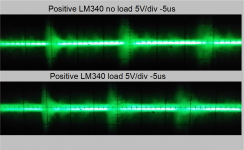
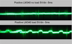
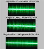
Here are some pictures of measurements. Does anyone see anything bad going on? The load was 98.77ohms. +/-15V regulators' output.
Here are some pictures of measurements. Does anyone see anything bad going on? The load was 98.77ohms. +/-15V regulators' output.
Attachments
Hi Jack,
Now that is one cool PSU tester! I do mine a little differently by injecting the noise or sawtooth into the error amp of the input regulator feeding the test supply. The current draw pulses are created with a DC amplifier feeding a 0.511 ohm resistor from the test supply. Fred Dieckman's regulator tester really sparks some ideas.
Many thanks to both of you on that!
Hi shredhead,
To size the required capacitance, you have to know the approximate peak load. For us old folks, the accepted method was to use 1,000 uF for each ampere of current flow. The exact answer is this. At peak load current and minimum line voltage, your regulator should never "drop out". You would see that as ripple-like dips in the regulated voltage output. You want to leave some headroom to allow for deterioration of your filter capacitors.
The simple fact is this. Low frequency ripple is much, much easier to get rid of than radiated current spikes (hence the reference to an AM radio). That means low frequency ripple on the input to your regulator is okay. Just like an audio amp (since we are drawing parallels), the regulator has more gain at lower frequencies (ripple) and therefore will attenuate that much more than higher frequency noise.
Eli, thanks for reminding me about the AM radio trick. I had forgotten it.
No, that would be unusual. Most electronic equipment use distributed capacitance to control noise radiation.Is it true that parallel caps on the PSU out and the electros on the PCB decoupling will oscillate if you don't use a snubber?
To size the required capacitance, you have to know the approximate peak load. For us old folks, the accepted method was to use 1,000 uF for each ampere of current flow. The exact answer is this. At peak load current and minimum line voltage, your regulator should never "drop out". You would see that as ripple-like dips in the regulated voltage output. You want to leave some headroom to allow for deterioration of your filter capacitors.
The simple fact is this. Low frequency ripple is much, much easier to get rid of than radiated current spikes (hence the reference to an AM radio). That means low frequency ripple on the input to your regulator is okay. Just like an audio amp (since we are drawing parallels), the regulator has more gain at lower frequencies (ripple) and therefore will attenuate that much more than higher frequency noise.
Eli, thanks for reminding me about the AM radio trick. I had forgotten it.
Awesome, thanks jitter. That is a serious scope you have there.
Thanks for pointing that out about the feedback causing oscillations, I didn't think of that. Nevermind on the pics of unregulated then.
Thanks, it's good to have access to such a scope as I wouldn't want to buy one myself. They're pricy but for years now they have been easily a lot better than the competition in that price bracket.
But however good a scope is, it's really easy to use it wrong, especially when trying to measure low level signals in the most sensitive settings. Than EVERYTHING becomes a big issue. E.g. the clip on earth lead, no good. It acts as an antenna and easily picks up quite a lot of noise. It's then that you realize what some of the small accessories supplied with probes are actually for....
I've been following EEVblog's channel on Youtube for a while now, and I learned quite a lot. If you're interested, this is a nice video to watch. And he has a lot more videos explaining some of the pitfalls of using oscilloscopes...
Sorry, I forgot to get the capture of the oscillating LM337. I'll try not to forget tomorrow.
It shows really strong oscillations caused by a design error, not low level noise. In that particular design, the combined ESR of the tantalums on the output was too low.
Hi jitter,
Yes, really, really nice 'scope! Some day .... The cost of the options on the DSO-X 3054A are pretty scary. But they do transform those 'scopes. Anything special on the one you are using? Is it allowed to come to your place for sleep overs?
I was insanely lucky and picked up an Agilent 54642D (MSO) very recently. It's soooo nice to have a really good 'scope! I'm keeping the Tek 2465B though. There are things an analog scope simply does better than a digital 'scope. I even have an old Gould (~15 MHz) for when I work on tube amps. It's so easy to kill a new DSO.
-Chris
Hi Chris,
AFAIK no special features are installed, but I don't really need any.
A colleague works a lot on broadcasting equipment, he has an even nicer 6000X series. I remember when we unpacked it that we were a bit astounded by the size of the display. The pictures on the website didn't really do that justice. That one does have some options installed, but I would have to check.
Sadly, I'm not allowed to borrow it. At home I have a 20 MHz Philips PM3208, but the switches are worn and the signal keeps dropping out.
I'm looking into buying something from Rigol...
Hi jitter,
Not wanting to hijack the thread here ...
The 6000 series was my favorite, but now the 4000 series has touch display. I have had a chance to play with the 3000, 4000 and 6000. Even the 7000 with the giant display. They are all simply wonderful. A new feature is the ability to capture a waveform, then the 'scope can "play it back" out a BNC jack. Ever cool! I also won a top of the line hand held multimeter. Fantastic unit!
Watch your government assets disposal people. That is where I got mine, and your government should also have such a department. Also, the company you work for probably has a way of getting rid of equipment they don't use anymore. It would be in their benefit to release those items to employees. Your skill goes up, your worth goes up.
I had some Philips 10 MHz 'scopes a long time ago. Very good units with very sharp traces. Often the switches would become noisy (even Tektronix). I had to clean them by hand and a nearly bald "Q-Tip" with contact cleaner. You can get those switches in great condition again. My Tek 2235, 465, 468 - all scopes, they all needed contacts cleaned except for the Philips PM3070's. Maybe they didn't get old enough before they died outright. Each needed a power supply rebuild. I will say that the Rigol units are okay, but the input voltage range is small. Easy to kill by mistake. These days aI m very, very careful with the new products. My Agilent cost less than many Rigol 'scopes, so research alternate sources before buying new. I have had poor luck with Ebay though.
-Chris
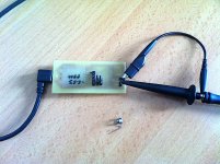
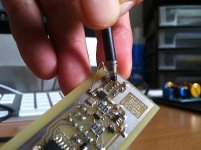
Beside having oscilloscope it is more important how you will make the measurements as there are many problematic point especially if you looking for some low values of signal or working with high speed signal.
Here is one practical example how you can be fooled to have "something" in your signal but after considering the effect of parasitic inductivity of just 10-15cm GND cable of oscilloscope probe you can have much clear picture.
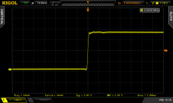
First and second picture show standard way to measure something and results of that measuring, but that is not correct for some application. Other two picture show correct method for most application.
PS: this is example of measuring high sped signal which have about 1500V/us slew-rate. Such high slew rate can be found in almost every SMPS and it is very important to use proper method. Similar is with measuring (AC coupled) noise or ripple of some linear regulator.
Here is one practical example how you can be fooled to have "something" in your signal but after considering the effect of parasitic inductivity of just 10-15cm GND cable of oscilloscope probe you can have much clear picture.
First and second picture show standard way to measure something and results of that measuring, but that is not correct for some application. Other two picture show correct method for most application.
PS: this is example of measuring high sped signal which have about 1500V/us slew-rate. Such high slew rate can be found in almost every SMPS and it is very important to use proper method. Similar is with measuring (AC coupled) noise or ripple of some linear regulator.
Attachments

Last edited:
- Status
- This old topic is closed. If you want to reopen this topic, contact a moderator using the "Report Post" button.
- Home
- Amplifiers
- Power Supplies
- What does preamp PSU oscillation look like for linear regulators?