Hi All,
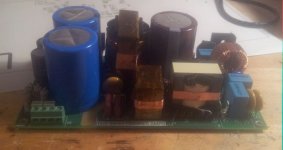
I have finished building a 1kW SMPS with PFC that I designed to power up
my class AB audio amplifier.
The main characteristics are:
Input voltage: 180...265VAC
Output voltage: +/-55VDC
Output current: 10A/rail --> total output power 1.1kW
Topology: ZVS Series resonant half bridge with BCM PFC. The switching
frequency is the tank resonant frequency or slightly above it
to ensure ZVS of bridge FETs. The output voltage is not regulated
and basically tracks the PFC voltage (385V) which is loosely
regulated.
Resonant frequency: 100kHz
PFC Voltage: 385VDC
Magnetic parts
----------------
Transformer: core: ETD44 3F3 no gap material
primary: 28T 100x0.1 Litz wire
secondary: 2x8T 200x0.1 Litz wire
Resonant choke: core: PQ2625 3C90 material
inductance: 27uH gap adjusted for proper L
winding: 18T 120x0.1 litz wire
PFC choke: core: PQ3230 3C90 material
inductance: 100uH gap adjusted for proper L
winding: 30T 120x0.1 litz wire
Note: this SMPS is designed for peak power of more than 1kW, is not intended for continuous use at 1kW (transformer too small....).
I have finished to build it but not yet powered up.... I am a bit scary of what can happen if something goes wrong....
Comments and questions are welcome.
ciao
-marco
Attachments
Since you already use two resonant caps, why dont you use a split capacitor layout + 2 fast diodes antiparallell, then you will have a shortcircuit proof design
( google for split cap llc , or look into the usual appnotes)
Did you add c17 and c27 to stabilize coss to have a better control of nevessary deadtime?
( google for split cap llc , or look into the usual appnotes)
Did you add c17 and c27 to stabilize coss to have a better control of nevessary deadtime?
Hello rikkitikkitavi,
you are right, I did not thought about it... but now the PCB is done.
The small 100pF caps on the FETs are there but not mounted.
On the PFC FET they are used to limit the dv/dt if needed on the bridge
are there just because there was place but I don't think that 100pF really matters here.
you are right, I did not thought about it... but now the PCB is done.
The small 100pF caps on the FETs are there but not mounted.
On the PFC FET they are used to limit the dv/dt if needed on the bridge
are there just because there was place but I don't think that 100pF really matters here.
No probably yoou wont need the 100pF caps. The internal capacitance of the fets is about 3-500 pF (or something) and since you use CFD (fast recitifer tailored towards the resonant converter) it will give you are more reliable converter
(there is plenty of white papers from semiconductor manufacturers describing why it is a good idea to use THEIR proprietary low Qrr,Fast Trr body diode mosfets for resonant converters but in principle it is same same but different...)
Awaiting first power up.
Good luck and no smoke!
Ps - try to start the PFC first with a resisitve load...
Ds-But one thing I dont understand, without feedback how do you control the resonant frequency ? Or did I missunderstand so that it is constant frequency and constant duty cycle?
regards
Rickard
Right, some google fu gave this old app note. Will read...
http://www.ti.com/lit/ml/slup085/slup085.pdf
http://www.ti.com/lit/ml/slup085/slup085.pdf
In fact it is always an llc but the magnetizing inductance is much higher than the resonant inductance.
If the frequency is set at f0 we are at the load independent point where the output voltage does not change with load current (except losses). I don't understand your point about primary inductance changing with load.
The frquency is locked at f0 so that the output voltage will be vout=vpfc/n since the gain of the llc tank is practically 1 at f0
ah, yes youhave two fr, one including the magnetising inductance and the other not.
Sorry for beeing unclear, with reflected inductance I meant all stray and leakage at primary side and reflected from secondary side to primary, so in practice your resonance frequency will be sligthly lower(I guess 27uH will be about 30-35uH). But you err on the high side, just dont loose your zvs
..
How is your xformer wound?
The transformer has around 2.5uh of leakage inductance. It is wound in this way:
- bobbin
- secondary 1: 8 turns 200x0.1 litz wire
- primary: 28 turns 4x0.65 tex-e wires in parallel
- secondary 2: 8 turns 200x0.1 litz wire
- aux winding: 3 turns 0.2mm tex-e wire
I have started testing it, the PFC works fine, tested up to 600w with resistive load.
The llc has some problems with the self supply; due to the big output capacitance the output
Volrage and thus the auxiliary voltage rises slowly. The auxiliary voltage being too low the smps continuosly starts and stops. Now I have added another auxiliary winding on the resonant choke that will supply the controller when the output voltage is low. Not yet tested it but from simulation it seems to work fine.
Regading loosing zvs I don't think it will be able to keep zvs at no load or very light load, the magnetizing inductance is too high. Possibly the transformer can be gapped to increase the reactive current keeping it always in zvs like a standard llc converter. I will see if it worth to be done-
Hi All,
I have finished to build it but not yet powered up.... I am a bit scary of what can happen if something goes wrong....
Comments and questions are welcome.
ciao
-marco
Power it up with a light bulb in series with the mains.
That's will limit the current it can take.
Hello @mag
I'm glad to see your LLC as we are on same course, in my case with FSFR2100")
First it is a really pity you didn't put FB, that occupied only about 10mm^2 of area on PCB with for example FOD2741.
@rikkitikkitavi mentioned diodes, that is used for clamping of voltage on resonant capacitors to voltages (almost) equal to HB voltage. That is one way of limiting the power and somehow protection from large capacitive load as you have (btw why you need such large capacity?). That can help but not ultimately protect your converter as that diodes can be very easily over-discipataed.
Next, F0, it is "nominal" working frequency but that frequency usually need to be changed as load (Q) changes. Also as you don't have FB, some problems can arise due LLC tank component tolerance and temperature changes.
Next, again pity you didn't makes integrated transformer (L4 + TR1) as that will be much much easier to build than this approach with separate component where TR1 need to have strongly coupled windings.
Must ask you, how you observe ZVS behavior? That is very tricky to track and I don't see on current schematic how you will do that!?
Usually on PCB is planed place for one resistor at HB output (later replaced with jumper) where you observe with two channels oscilloscope voltage on both side of that resistor in order to find absolute minimum (the most critical parameter!!!) and maximum working frequency. But again, you don't have FB and have large capacity load, that is very problematic.
At a moment I can help you with this (attachment) simplified LLC LTspice simulation where you can observe different parameters against frequency sweep.
Second attachment is commented PDF document with graphs where you can see the regions where ZVS take place (take an look on red line). I'm sorry for Serbian language in that PDF but you will get the point.
--
@nigelwright7557
That with light bulb is wrong "myth"! In most situation with SMPS that can't help as in bulk capacitor on PCB have enough energy to destroy the most powerful transistor in microseconds if something goes wrong
We need several order faster protection!
I'm glad to see your LLC as we are on same course, in my case with FSFR2100
First it is a really pity you didn't put FB, that occupied only about 10mm^2 of area on PCB with for example FOD2741.
@rikkitikkitavi mentioned diodes, that is used for clamping of voltage on resonant capacitors to voltages (almost) equal to HB voltage. That is one way of limiting the power and somehow protection from large capacitive load as you have (btw why you need such large capacity?). That can help but not ultimately protect your converter as that diodes can be very easily over-discipataed.
Next, F0, it is "nominal" working frequency but that frequency usually need to be changed as load (Q) changes. Also as you don't have FB, some problems can arise due LLC tank component tolerance and temperature changes.
Next, again pity you didn't makes integrated transformer (L4 + TR1) as that will be much much easier to build than this approach with separate component where TR1 need to have strongly coupled windings.
Must ask you, how you observe ZVS behavior? That is very tricky to track and I don't see on current schematic how you will do that!?
Usually on PCB is planed place for one resistor at HB output (later replaced with jumper) where you observe with two channels oscilloscope voltage on both side of that resistor in order to find absolute minimum (the most critical parameter!!!) and maximum working frequency. But again, you don't have FB and have large capacity load, that is very problematic.
At a moment I can help you with this (attachment) simplified LLC LTspice simulation where you can observe different parameters against frequency sweep.
Second attachment is commented PDF document with graphs where you can see the regions where ZVS take place (take an look on red line). I'm sorry for Serbian language in that PDF but you will get the point.
--
@nigelwright7557
That with light bulb is wrong "myth"! In most situation with SMPS that can't help as in bulk capacitor on PCB have enough energy to destroy the most powerful transistor in microseconds if something goes wrong
We need several order faster protection!
Attachments
@ mag
looks nice indeed.
You said
(The output voltage is not regulated
and basically tracks the PFC voltage (385V) which is loosely
regulated.)
That means the PFC output voltage is NOT fully regulated with load?
When you load / unload the PFC?
I also don't understand why the input voltage is 180 ~ 265VAC, while it must be 90~265VAC, thats why the PFC is in there.
@mag
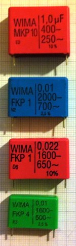
Just another note regarding C34 and C35, due very large circulating current (order of 10 to 30A @100kHz) in resonant tank, you need the best quality capacitors you can find, for example Wima FKP1 (best), then FKP4 or MKP10 which have lowest dissipation factor, something likes as shown on picture in attachment.
Other capacitors will have very short life or they can simple explode after few minutes/hours of work in high-load condition!
Attachments
Yu3ma, you mentioned that measuring the voltage over a series resistor out from the bridge FETs can be used to monitor ZVS , and such is it drawn in your LTspice file(yes sir, thank you for that, now playing at my PC )
I just want to point out that the powersupply must then be isolated from the wall outlet, otherwise it will share ground with scope ground and thus measuring at the switch node connects this to ground.
Using floating differential measurement with two probe tips cause the problem of isolation voltage and still the scope ground is at Earth potential.
floating the scope by battery power or isolating transformer means that scope ground and chassis rest at live potential, a dangerous situation. It is possible but unadvisable, if you touch any scooe ground parts you get a good smack atleaSt.
Therefore-always use a isolation transformer powering any equipment under test(EUT) , or when broken and at.repair atemps (JUT, Junk Under Test)
rikkitikkitavi,
Yes, isolated transformer for oscilloscope is a MUST when working with SMPS on primary side to overcome grounding issues.
In addition another (separate) isolating transformer is advised for powering DUT for own safety.
BTW: You probably know but just to mention, DO NOT touch gates of primary transistor with probe while converter working!
Regarding LTspice model I provided, that is just a simplified schematic of LLC circuit, mostly for educational purpose to observe and learn different behaviors against frequency.
For example you can change output filter capacitor and put some large values (for example 10.000uF) to see what will happened on highest operating frequency … If OCP in circuit is not working or wrongly projected or you change working frequency too fast that usually leads to kaboooommm
Same things for lowest operating frequency in a case of short circuit on secondary side, another kaboooommm (explosion of primary transistors) …
Large capacitive load is very problematic and need to take special care on it. Soft start is one method to overcome such issues.
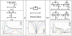
More efficient way is to implement band-stop (notch) filter in resonant tank! That is very interesting approach as you can have "safe" area for converter where you can "put" your converter in an case of large load. Consequence using this notch filter is that current sensing along with voltage sensing is required on secondary side, BUT that can be very useful, finally we can build LLC converter which can have 0-100% current/voltage regulation, which is not possible without it!!!
Try this (in attachment) LTspice schematic, version with notch filter. Note Rac resistor which is idealized secondary side circuits.
Yes, isolated transformer for oscilloscope is a MUST when working with SMPS on primary side to overcome grounding issues.
In addition another (separate) isolating transformer is advised for powering DUT for own safety.
BTW: You probably know but just to mention, DO NOT touch gates of primary transistor with probe while converter working!
Regarding LTspice model I provided, that is just a simplified schematic of LLC circuit, mostly for educational purpose to observe and learn different behaviors against frequency.
For example you can change output filter capacitor and put some large values (for example 10.000uF) to see what will happened on highest operating frequency … If OCP in circuit is not working or wrongly projected or you change working frequency too fast that usually leads to kaboooommm
Same things for lowest operating frequency in a case of short circuit on secondary side, another kaboooommm (explosion of primary transistors) …
Large capacitive load is very problematic and need to take special care on it. Soft start is one method to overcome such issues.
More efficient way is to implement band-stop (notch) filter in resonant tank! That is very interesting approach as you can have "safe" area for converter where you can "put" your converter in an case of large load. Consequence using this notch filter is that current sensing along with voltage sensing is required on secondary side, BUT that can be very useful, finally we can build LLC converter which can have 0-100% current/voltage regulation, which is not possible without it!!!
Try this (in attachment) LTspice schematic, version with notch filter. Note Rac resistor which is idealized secondary side circuits.
Attachments
Last edited:
Hi all,
Thank you for your comments.
The smps is purposely not regulated and designed to work at around f0, it is not a matter of saving some cents for opto feedback. The PFC is regulated at 390v but like every pfc regulator its transient response is slow. The purpose of this project is to replicate the behavior of a 50hz transformer plus rectifier and bulk capacitors but at a much smaller size. In a circuit like that with very high Lp the regulation will be very hard to achieve at low load. If I wanted to build a standard regulated LLC converter Lp should be in range of 100...200uH and not 2mH as it is now. This is done on purpose to see what happens keeping the frequency at f0 thus in the ideally load independent point. I have no need to be short circuit protected even though a current limit is p2resent to manage sudden load transients. The frequency will never change so that the converter can never go into capacitive mode potentially hazardous for the primary FETs.
In this circuit there should be no limit on the available power except thermal issues and saturation of the resonant choke; the OCP is set so far away from the saturation.
Dead time: In my circuit I don't think I will be able to keep ZVS at no load ( not enough reactive current to discharge Coss due to high Lp). I am hovever using FETs with fast body diode so that it has to be checked if it is a real issue. In case the transformer can be gapped to reduce Lp and increase the reactive current to reach ZVS.
Capacitor: wima FKP is in my opinion the best capacitor available for this application; they are however quite bulky. The current in each capacitor is 3.2Arms at 1kW load. I am using Panasonic ECWF 47nF 1000v which is rated 3.5A @ 100kHz. Taking into account that it is used to power an audio amp the average power will be much lower than this so I think that I am on the safe side. Wima FKP was not available otherwise it will be my tirst choice.
Light bulb: it is true it does not save you from blowing FETs if something goes wrong, the energy stored in the primary capacitor is probably 1000 times what is needed to blow it..... however it can save you a lot of troubles because you don't have a dead short on the mains with energy much greater than the one in the capacitor.
Notch filter: nice idea but:
- the Q of the notch will be quite high; how can you instruct the contoller to go at the notch frequency during short circuit?
- what about the voltage on the notch capacitor when fsw=fnotch? Does it stay at reasonable values ?
- why complicate things so much? LLC is already a very complicated topology with lots of operating modes depending on frequency voltage and load adding another resonance will for sure further complicate everything another step further.
- how do you compensate such notch, it will have some effect on the converter transfer function and your compensator must take if into account to have the proper phase and gain margin at closed loop.
-the standard method to deal with short circuit is to increase the switching frequency if an overcurrent is detected; is it not safe enough? With new llc controller that check also the phase of the tank current with respect to the bridge voltage is not possibile to enter into capacitive mode with all the related troubles. See for example L6699 from ST or other controllers from NXP that implement that function.
Notch filter: nice idea but:
- the Q of the notch will be quite high; how can you instruct the contoller to go at the notch frequency during short circuit?
- what about the voltage on the notch capacitor when fsw=fnotch? Does it stay at reasonable values ?
- why complicate things so much? LLC is already a very complicated topology with lots of operating modes depending on frequency voltage and load adding another resonance will for sure further complicate everything another step further.
- how do you compensate such notch, it will have some effect on the converter transfer function and your compensator must take if into account to have the proper phase and gain margin at closed loop.
-the standard method to deal with short circuit is to increase the switching frequency if an overcurrent is detected; is it not safe enough? With new llc controller that check also the phase of the tank current with respect to the bridge voltage is not possibile to enter into capacitive mode with all the related troubles. See for example L6699 from ST or other controllers from NXP that implement that function
ZVS check:
Why do you need such resistor? Simply check your low side FET vds and vgs. Check if vgs goes high after vds goes to 0V so you have a zero voltage turn on. You can even check for that only looking at vgs: there should be no Miller plateau and you will see a small negative spike before the rise of vgs due to the current injected by Cgd before the turn on.
Input voltage range: in theory in can operate from 85Vac but the PFC inductor is not rated for that. At low line and with 1kW power the inductor will saturate possibly destroying the PFC FET. If you want to operate at low line with such power the PFC inductor must be much bigger than this.
Last edited:
- Status
- This old topic is closed. If you want to reopen this topic, contact a moderator using the "Report Post" button.
- Home
- Amplifiers
- Power Supplies
- 1kW resonant SMPS