Hi all, I'm looking at trying to make a cyrus psx clone, as far as I can tell its a +/- 38V unregulated supply, and from looking at the innards of my fathers its a 500VA torroid, 4x15,000µF slit foils and then dual rectifiers.
So, that all said I was planning on 4x 22,000µF slit foils [bit pricey], I need to work out what would be suitable diodes, I cant really tell if there would be any real appreciable difference between getting some ultra-fast soft recovery's and using one/ of these GBPC2504 - FAIRCHILD SEMICONDUCTOR - BRIDGE RECTIFIER, 25A, 400V | CPC
The main question finding a transformer that has the necessary 27v secondaries is a bit of a pain, if I use a trafo with 30v secondaries will the 42v output of the PSX cause issues inside of the Cyrus or do I not need to worry about it too much?
Also anyone care to throw any opinions on the idea of bypassing the large slit foils with smaller value caps?
Thanks!
Edit missed this link, but basically I'm just planning to follow the diagram as show here http://sound.westhost.com/psu-wiring.htm and suit it to my needs.
Last edited:
buy a 500VA or 600VA 230:25+25Vac dual secondary transformer.
Measure your mains voltage.
You will end up with a 26+26Vac transformer.
Now if you want you can add two windings around the toroid.
About 5Turns to 10Turns will give plenty of voltage to add on to the two existing windings.
The capacitors are so far away from the amplifier due to the umbilical that HF response of the main smoothing capacitors is in my opinion not important.
Good quality standard commercial capacitors will be good enough. Epcos make small cheap good electros. I have 25V, 35V and 50V versions.
The local decoupling inside the amp chassis and on the amp PCB are far more important to the HF performance of the amplifier.
Do you know how the two extra pins in the umbilical work?
I don't.
Have a look at the TNT site for more and deeper PSU explanations.
Last edited:
Thanks for your reply, I've also had a look at the schematic on the TNT website, but some comments ive seen regarding it bring up the issue of there being greater voltage drop on the rails because of using dual rectifiers - what would be the purpose of adding two extra pins to the umbilical cord? If I wanted to i could just replace the mini-xlr on the cyrus and use an appropriate connector for it.
Interestingly reading the service manual it claims that the PSX routes power through to the two 10,000µF capacitors inside of the cyrus 2, so in theory if someone is renovating/ building a PSX they ought to also pay attention to the internal caps as local decoupling - AndrewT would you suggest bypassing those caps with smaller value caps as opposed to the very large ones that would be in a PSX?
the standard plus is 3 pin mini-XLR - +38v -38v and ground
Mine has a 5 pin mini XLR plug with + / - 38 and ground plus two 'spares'.....
Bypasses across electrolytics are likely to increase the risk of ringing in the supply.
This would be more likely when low esr electrolytics are used.
Is slit foil a low esr electrolytic?
DON'T !!
Might be worth looking carefully at how Cyrus have implemented local decoupling.
There could be improvements waiting to be done in there.
This would be more likely when low esr electrolytics are used.
Is slit foil a low esr electrolytic?
DON'T !!
Might be worth looking carefully at how Cyrus have implemented local decoupling.
There could be improvements waiting to be done in there.
building a cyrus CDP PSU
Zibidezeb thanks. I’ve been looking everywhere for this.
Flushed by the success (and improved sound quality) of building and stuffing four super-regs in my nac72. I have decided to build a PSU for my Cyrus CD8x.
I’ve been trying to find out how the units (PSX-R and CDP) communicate with each other and what causes the CDP to disengage its internal supplies to the transport and use the external one. CDP needs +-21V not +-38 like the Amps. Cool.")
So I need to build a supply with +-21v, Gnd and +5v. I could also fit a subcircuit with a relay that deactivates the main PSU if pin 1 goes to logic state 0 (CDP in standby). Thanks
Zibidezeb thanks. I’ve been looking everywhere for this.
Flushed by the success (and improved sound quality) of building and stuffing four super-regs in my nac72. I have decided to build a PSU for my Cyrus CD8x.
I’ve been trying to find out how the units (PSX-R and CDP) communicate with each other and what causes the CDP to disengage its internal supplies to the transport and use the external one. CDP needs +-21V not +-38 like the Amps. Cool.
So I need to build a supply with +-21v, Gnd and +5v. I could also fit a subcircuit with a relay that deactivates the main PSU if pin 1 goes to logic state 0 (CDP in standby). Thanks
the standard plus is 3 pin mini-XLR - +38v -38v and ground
is not a mini xlr plug but a hirose plug
Cyrus PSX P/S sevice manual images
I have the actual complete "Mission" Cyrus service manual, obtained directly from Mission in 1989. I can make / take images and/or "copy" other aspects / pages if needed.
I have wanted to build a PSX ~forever~ (too many other projects)
I have the actual complete "Mission" Cyrus service manual, obtained directly from Mission in 1989. I can make / take images and/or "copy" other aspects / pages if needed.
I have wanted to build a PSX ~forever~ (too many other projects)
Attachments
OZark I really really appreciated, thank you;I have the actual complete "Mission" Cyrus service manual, obtained directly from Mission in 1989. I can make / take images and/or "copy" other aspects / pages if needed.
I have wanted to build a PSX ~forever~ (too many other projects)
I know that someone has built it with a pcb like these (using half of it)

with a dual 30V transformer, diodes and 4 capacitors;
I don't know how to connect a dual 30v to that ocb..
Thank you again
Choices to build approach(es)
You are welcome, it may be redundant, others may "already now this", what is specified / needed (that exact detail) to build, and the thread is old... I figured I would put it out there anyway.
*Antek makes *a perfect* transformer, may only apply to those that are in the US (not sure if they ship internationally) AN-5428 - 500VA 28V Transformer.
**I am sort of "off" toady (not feeling good) cannot reason your words, or wrap my mind around the PCB posted... but my first thought would be to parallel the secondaries to the "single" power supply (as shown). Granted, I may not be understanding what you are working with, your particulars...
I am trying to get away from PCB based power supplies [this is just me] in favor of beefy point to point wired P/Ss, any prospect(s) of current limiting.
OZark I really really appreciated, thank you;
I know that someone has built it with a pcb like these (using half of it)
with a dual 30V transformer, diodes and 4 capacitors;
I don't know how to connect a dual 30v to that ocb..
Thank you again
You are welcome, it may be redundant, others may "already now this", what is specified / needed (that exact detail) to build, and the thread is old... I figured I would put it out there anyway.
*Antek makes *a perfect* transformer, may only apply to those that are in the US (not sure if they ship internationally) AN-5428 - 500VA 28V Transformer.
**I am sort of "off" toady (not feeling good) cannot reason your words, or wrap my mind around the PCB posted... but my first thought would be to parallel the secondaries to the "single" power supply (as shown). Granted, I may not be understanding what you are working with, your particulars...
I am trying to get away from PCB based power supplies [this is just me] in favor of beefy point to point wired P/Ss, any prospect(s) of current limiting.
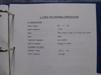
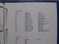
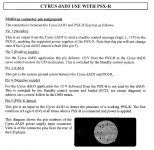
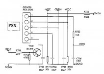
I looked into how to clone a PSX-R as well because I want to power my Cyrus Dacmaster with a diy PSU, and found the following information:

Page 6 tells us the wiring, maybe PSXO and AMPIN could be points inside the PSX-R:

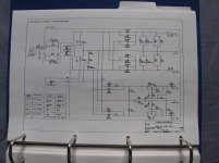
I assume that with PSXO they mean pin5 of the Hirose connector and with TR700 they mean T700 shown in the diagram below:

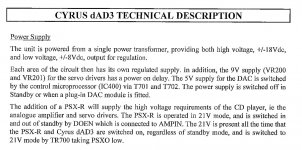
These screenshots are taken from the DAD3 service manual but should explain how to get around the PSU detection.
I made a test by pulling pin5 low (by shorting pin3 to pin5 on the Hirose connector) but the Dacmaster still played music through the outputs: do I need to supply also +/-21V to pin2 and pin4 in order to make the DAC detect the presence of an external PSU?
Page 6 tells us the wiring, maybe PSXO and AMPIN could be points inside the PSX-R:
I assume that with PSXO they mean pin5 of the Hirose connector and with TR700 they mean T700 shown in the diagram below:
These screenshots are taken from the DAD3 service manual but should explain how to get around the PSU detection.
I made a test by pulling pin5 low (by shorting pin3 to pin5 on the Hirose connector) but the Dacmaster still played music through the outputs: do I need to supply also +/-21V to pin2 and pin4 in order to make the DAC detect the presence of an external PSU?
Attachments
- Home
- Amplifiers
- Power Supplies
- Building a Cyrus PSX