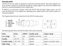
AMPIN and PSXO are pins on the Hirose connector:

Seee page 26 of the Cyrus Pre (type HA7L) pre service manual. I also found the PSX-R service manual explaining the communication needed on pin1 and pin5 on page 4:

Seee page 26 of the Cyrus Pre (type HA7L) pre service manual. I also found the PSX-R service manual explaining the communication needed on pin1 and pin5 on page 4:
Attachments
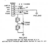
I made some more tests with my Cyrus Dacmaster: pin1 outputs 0V when the DAC is in standby and 5V when it's on, pin5 is hard wired to 0V, so both of these pins can be ignored. Positive and negative external supplies to pin2 and pin4 are not switched by a relay: instead there are parellel diodes for the internal and external supply voltages. If the external supply voltage is higher than the internal supply voltage the diode of the internal supply voltage becomes reverse biased and shuts off. So there is no switching needed at all: just connect +21V to pin2 and -21V to pin4 of the Dacmaster.