Hmm.. maybe an orange and an infrared? Or a green and an infrared when bit short from target. If you haven't got any IR LED in hand, an old useless remote control could donate one.
Spot on, on the first try.
") One kingbright orange and WP7113F3C Kingbright | Mouser Sverige
One kingbright orange and WP7113F3C Kingbright | Mouser Sverige 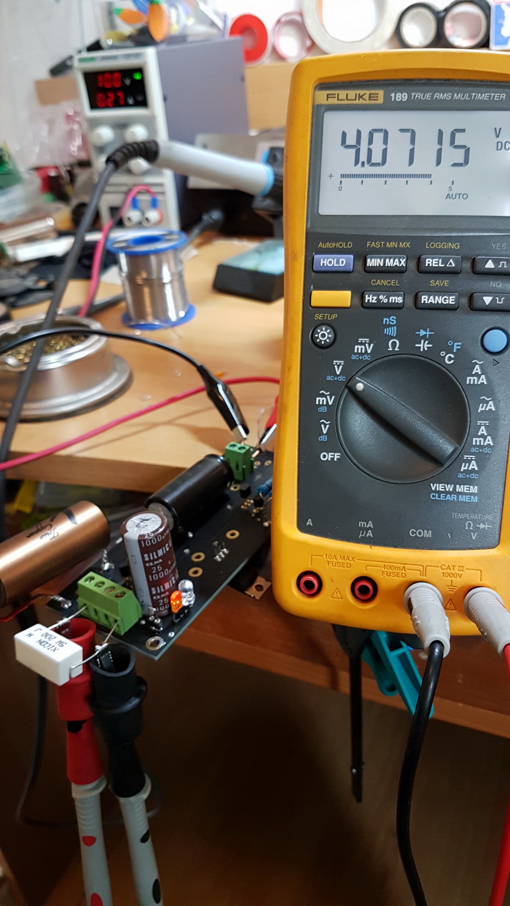
Congrats dahlberg. How it sounds?
I have never heard it. It's a part of a multichannel dac that never seems to be finnished. I'm slowly getting there though

Hello Salas, i need some help.
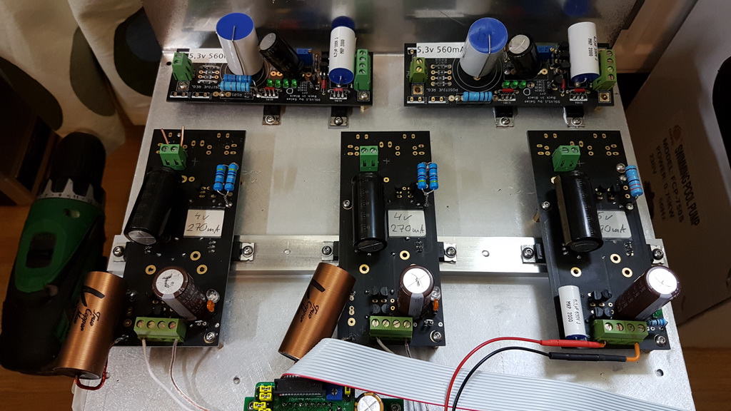
I build 3 reflektors for my dac and xmos. i am trying capacitors for c2 up to 10.000uf of polymer type as for suggestion on and earlier post long time ago.
1º build for 3.3v R1:2Ohm (dac) - i used for c2: 1000uf x4 +2200uf x 2 = 8400uf (seems ok) temperature on sinks 38ºc
2º build for 3.3v R1:2Ohm (dac)- i used for c2: 2200uf x 4 +1000ufx1 =9800uf ( everything seems ok but when i turn of the power off the green led takes a lot of seconds to go complete black...) temperature on sinks 38ºc
3º build for 5v R1:1Ohm (this is for xmos usb side only)- i used for c2: 2200uf x 4 +1000ufx1 = 9800uf (here something happens when i turn the power on the two green leds take some 6 or 7 seconds to light up) temperature on sinks 50ºc after stabilize
for 3.3v i use 7vac and for 5v i use 9vac.
What do you think about the temperature of the 3º build - the leds only shine after 6 or 7 seconds on power on??? should i change r1?
i´m happy with the sound, and i´m using r6 vishay var. i´m starting to build one more for the clocks on the xmos board and im using UBIB on the vrefs os the dac also.
Last edited:
Those long times can be explained due to the high Vref filtering capacitance choices. If the loading during off is zero in a rail than in another rail that still draws until a threshold, it will take longer for its Leds to extinguish than in the other rail. And vice versa.
5V to be reached takes longer than 3.3V which is much nearer to the output Mosfet's threshold for instance. There is little current charging the Vref capacitance and its also a little current bleeding through Leds to discharge the big caps when powering off.
About 50C you could moderate the main CCS setting, but best is to first confirm what is the constant current and the consumption by measurements. It could be already well set but simply heating higher than the other builds because there is more Vin-Vout due to the transformer.
In my experience it likes 200-300mA spare better. But 120mA spare is a technically competent setting already. Decide by weighing the dissipation results in your application. In any case don't ever set for below 100mA spare current. It begins goofing below that threshold.
Looking to use 2SK880GRTE85LF for J1. Few questions:
- The board is already compatible with SMD jfet? Doesn't look like I need an adaptor board.
- According to mouser spec ID is 14mA - should I double check for ones with lower ID or it should be ok?
I measured some several years back.
Typical idss was 5.5-6.0mA
I don’t remember them running that high with idss
Just figured it will be complicated to measure idss taking into account the size of it
Do you think I can assume it is ~6mA idss and soldier RR 100R?There are already alternative SMD pads for J1 on the REF-D board, yes. Located between J1 & Q5 on the top layer. The Mini version has such for J1 & J2 also but located on the bottom layer.
Thanks Salas for confirmation !
Just figured it will be complicated to measure idss taking into account the size of it
I would not actually. I would solder it on first and then try to get a measurement of it once installed on board and you can likely get a better grip on it. I did find them too difficult to work with. If I sneezed I would lose them all.
Might be the way of the future however.
- Home
- Amplifiers
- Power Supplies
- Reflektor-D builds