Hi Salas,
I need two 1.2V for supply the DAM1021 CPU and bias the digital isolation transformer.
If I use one Reflektor-D at 5V output and connect to two LM317 (set both output to 1.25V).
Will Reflektor-D stable in this application ? and safe to do so (connecting the output to another 3pins regulator) ?
Thank you.
Connecting REF-D's output to distributed chip regulators is stable as many already use it in such a master reg's role.
Prefer low noise modern LDO than 317 if you can. Like LT1963A in DCQ package which is easy to solder by hand despite surface mount.
Thank you for your advice.
Could you tell me the different between LT1963 and LT1963A ? Because I can get LT1963 easier than LT1963A.
TL1963ADCQT type is stable to ceramic output capacitor. Made by Texas its cheap enough in that package. The TPS7A4501DCQR is its alternative.
Bypass ceramics of high coefficient dielectrics have unstable characteristics vs bias voltage and temperature. But this is a concern in industrial grade.
You will use 10uF electrolytics of no more than 3 Ohm ESR very close to its input and output pins. You have to read the datasheet carefully anyway.
There is also the more expensive LT1963ET from Analog Devices/LT which is TO-220 and adjustable but not that tolerant to high coefficient ceramics.
Fixed output 3pin variety LT1963s don't come in lower preset than 1.5V unfortunately and are SMD only.
Hi, Salas, just want to say thanks for the wonderful design.
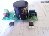
I like it so much that I had to make a version to accommodate Mundorf 4-pin cap as C2 capacitor to filter LEDs.
Also, it is very useful to keep those socket pins. Voltage can be changed to desire any time. Cheers.
I like it so much that I had to make a version to accommodate Mundorf 4-pin cap as C2 capacitor to filter LEDs.
Also, it is very useful to keep those socket pins. Voltage can be changed to desire any time. Cheers.
Attachments
Thanks Salas for you response.
can you explain me about the capacitors on reflektor-d...
for example i bought russian teflon 6800pf to use with r5 2.2ohm.
what do i need to measure or know about the specs for comparing it to the wima mkp10... or vishay 1837... how to i know they are better or not technically...
about the c2... i ´ve been reading some datasheets and i found values for ripple current and impedance at 100kh.. with increase of voltage the better the ripple current and impedance.. and what about esr?? should i measure the esr??
what are the important specs of the c2 to have in account when picking the c2 cap?
is the same aspects of c2 applied to cm?
best regards
Nuno
I would suggest you measure Q if you got a handheld LCR that can go high in frequency. The higher the Q number the better. Its easier to nail that parameter than D (dissipation factor) with such rather affordable meters of few digits display for their sub-parameters section when testing very low loss caps. Higher Q would mean lower loss at a given frequency.Thanks Salas for you response.
can you explain me about the capacitors on reflektor-d...
for example i bought russian teflon 6800pf to use with r5 2.2ohm.
what do i need to measure or know about the specs for comparing it to the wima mkp10... or vishay 1837... how to i know they are better or not technically...
about the c2... i ´ve been reading some datasheets and i found values for ripple current and impedance at 100kh.. with increase of voltage the better the ripple current and impedance.. and what about esr?? should i measure the esr??
what are the important specs of the c2 to have in account when picking the c2 cap?
is the same aspects of c2 applied to cm?
best regards
Nuno
C2 is a voltage reference filter not a reservoir so no concerns about ripple current, but low 100kHz impedance is nice to have. ESR is usually low too in such caps.
HI all
Apologie if it came up but I couldn't find it:
How do you calculate the transformer specs based on the CCS of the Reflektor?
I have two selectronic R-Cores with 2x15V and 2x9v secondaries, 0.8mA each (30VA total). What load could I hook up to one 9V secondary? (They actually measure 11VAC).
Thanks
ElEsido
adding up 2*15Vac*0.8Aac plus 2*9Vac*0.8Aac comes to 38.4VAHI all
Apologie if it came up but I couldn't find it:
How do you calculate the transformer specs based on the CCS of the Reflektor?
I have two selectronic R-Cores with 2x15V and 2x9v secondaries, 0.8mA each (30VA total). What load could I hook up to one 9V secondary? (They actually measure 11VAC).
Thanks
ElEsido
That is over your figure of 30VA.
Does that mean:
a.) the 0.8Aac is the maximum from any single secondary and that the total must not exceed 30VA?
or
b.) 30VA - 2*15Vac*0.8Aac = 6VA spare for the two 9Vac secondaries.
What have you got? a or b?
Sorry, my info was incomplete, the two 9VAC are 08.A each; the two 15V are 0.5A (but irrelevant for the project since the voltage is too high). It is one of these transformers of which I have two laying around:

2* 15VAC *0.5A = 15VA
2* 9VAC *0.8A = 14.4VA
Total ca. 30VA
In addition I have some spare 9VAC 08.A secondaries on an custom AYA DAC Transformer and I wonder if I need to parallel several secondaries for a Reflektor that powers Ian's PCM board, or if a single one would be up to the task.
The Reflektor Manual states that a 30VA transformer is required (with all 30VA being available for the Reflektor of course), but does not specify for which configured CCS this applies. Wouldn't a Reflektor configured for just 0.3A CCS be happy with a less potent transformer?
Hence I wonder: How do you calculate the minimal transformer power?
How's that?
W = ICCS*VDCout + ICCS*(VDCin-VDCout)
and
W+50% safety margin = VA of the secondary?
So in the example of the Reflektor for Ian's PCM board:
PCM Board Load: 4V, 50mA
Reflektor CSS 0.3A (R1=2ohm)
W=0.3*4+0.3*(12.6-4)=~3.8 [the 12.6 are the trafo's 9VAC rectified to DC; 9*1.41]
3.8W+50% -> 5.7VA
5.7VA ^= 9V, 0.633A
Is that plausible? (I am far from being an engineer and I have no gut feeling if what I am concocting here makes any sense...)
Last edited:
One 9Vac secondary has a maximum continuous output of 0.8Aac.
It tells you that on the label.
If you series connect the two 9Vac secondaries you get a maximum continuous output of 0.8Aac, but this time @ 18Vac
If you connect the two 9Vac secondaries in parallel you get a maximum continuous output of 1.6Aac, @ 9Vac
Using one 9Vac secondary gives you 7.2VA, using both 9Vac gives you 14.4VA.
But be careful.
The windings are colour coded. Check the phasing on the two limbs. And use a Mains Bulb Tester to power ON to save damaging this transformer. Use a low wattage bulb 28W ?
Last edited:
Thank you Andrew!
Do you have an view whether one secondary 9VAC 0.8A is enough to drive a Reflektor that is configured for 4V/300mA, or if paralleling two secondaries is required to get 9VAC 1.6A?
According to my calculation above a setting of 4VDC/300mA requires a trafo that delivers at least 9VAC/0.633A, therefore on secondary should be enough. HOWEVER I don't know if the way I calculated this is correct - can anybody double check, please?
When you have a continuous output of 800mAac, you can draw an approximate rating of 400mAdc to 500mAdc.
This would normally run the transformer at maximum temperature. But you are only using one secondary, the other three are generating no heat. The primary will also be well under it's maximum rating and so generate less heat.
I would guess that you would not need to de-rate further for cool operation. (I normally recommend one applies a 50% factor for cool operation).
You say you only need 300mAdc and this is under the continuous DC estimate for maximum current.
Last edited:
- Home
- Amplifiers
- Power Supplies
- Reflektor-D builds