thank you for reply
I ve read It but It Is meant for digital
can we lower C2 value to 470 uF If we use to supply analogue loads
My subjective best choice for analog was useing Mundorf 4pin AG+ 1000uf cap. In the post I described how to connect it. For digital I used Nichicon FPCAP 1000uf.
I experiment with lowering the value of C2 down to 100uf and using polypropylene cap, however results were not satisfactory for me.
I tried 2SK880-GR but in BiB. They are OK performance-wise and I did not notice any sound degradation. If you are wondering just go for them
Thanks. I will buy some and try.
Hi, Tio
I am thinking to use Mundorf Mlytic AG+ in C2.
I suppose in your connection, you lift the LEDs off ground by employing Mylytic's separate charging / discharging circuit (kind of decoupling). However, it looks like we should use in+ and in- to form a loop and then out+ and out- to form the other (decoupled) loop. Your connection seems to be different than Mundorf's description and than the connection on Salas' flexy. Could you double check?
Mundorf MLytic AG+ 4-Pole cap users : beware of wiring, some of us got it wrong ! | Audiokarma Home Audio Stereo Discussion Forums
Thanks.
WYAN
Try also Mundorf 4 pin Ag+ caps. They are excellent. Especially on C2 (1000uf) position
And as you already mentioned give some time to burn in.
So, for digital part of chips (DVDDs) I am using Nichicon FPCAP on C2 position (best 1/f filtering, but terrible tone). However for AVDDs, analog Vrefs or powering resistor ladders dac directly (Soekris R2R), generally places from where audio signal is produced from, Mundorf 4 pin I found to excel any other cap in this position.
Attachments
Hi, Tio
I am thinking to use Mundorf Mlytic AG+ in C2.
I suppose in your connection, you lift the LEDs off ground by employing Mylytic's separate charging / discharging circuit (kind of decoupling). However, it looks like we should use in+ and in- to form a loop and then out+ and out- to form the other (decoupled) loop. Your connection seems to be different than Mundorf's description and than the connection on Salas' flexy. Could you double check?
Mundorf MLytic AG+ 4-Pole cap users : beware of wiring, some of us got it wrong ! | Audiokarma Home Audio Stereo Discussion Forums
Thanks.
WYAN
The description you provide is for case when 4pin cap is used in PSU application.
The one I described is for LEDs filtering. It is tested and works. I got few reflectors working like that. I cannot imagine connect it any other way for LEDs.
The description you provide is for case when 4pin cap is used in PSU application.
The one I described is for LEDs filtering. It is tested and works. I got few reflectors working like that. I cannot imagine connect it any other way for LEDs.
Thanks. Scratching my head and trying to figure out ...
Thanks. Scratching my head and trying to figure out ...
Here is the drawing for correct wiring:
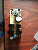
I possibly can post pics from my build if needed.
Attachments
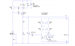
Here is the drawing for correct wiring:
I possibly can post pics from my build if needed.
Hi, thanks. I was thinking about a schematic like attached. It is just about pins.
Attachments
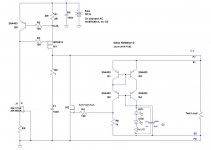
Hi, thanks. I was thinking about a schematic like attached. It is just about pins.
So I think yours is actually wrong. Have you tested such connection?
So I think yours is actually wrong. Have you tested such connection?
Hi, I have just ordered mlytic on the way. And like I said, I was confused and just trying to figure out how to connect the pins.
By the way, your PM box is full. Cannot send any PM in.
post1012
The current mirror has to pass current down through both sides.
You have broken the current route through the right hand side.
Then reconnected it via the capacitor's internal wiring.
Hi, Andrew,
You are probably right. And sure I don't have any idea about the inner structure of that cap. Maybe it is itself a very good cap even without taking advantage of the two-section construction. I will email Mundorf to find out. Thanks.
WYAN
Hello,
I just build a Reflektor-D with 12VAC transformer, J1(5,4mA IDSS, 82ohm RR) and J2 2SK880GR, FQP3N50C,FQP3P20 and LM329. Just with the LM329 and J2 IDSS 4,6mA(this one has the smallest IDSS from all my batch) I got initially 8,42V, now, after 4 hours of continuous running I get a constant 8,39V.
My target voltage was 8.00V but now I am thinking if I should get ride off the LM329 an try to achieve 8V using LED's or keep the LM329 and modify the design of the DAC to work with 8,39V. I am thinking that LM is better than LED's - please correct me if I am wrong.
With R1=2ohm, and DAC 80mA consumption, the heatsinks are only warm, and I am very happy about this
If for instance I want to go for 8,5V, if I use a J2 with ~6mA IDSS will that be ok, or I should stay to the recommended 2-4mA J2 IDSS?
Thank you !
Attachments
Unfortunatelly from my tests leds are better than lm329. Lm329 seems to generate more hf noise. To get 8V I would go 3 green with highest drop, one 1N4148 and jfet with highest idss.Hello,
I just build a Reflektor-D with 12VAC transformer, J1(5,4mA IDSS, 82ohm RR) and J2 2SK880GR, FQP3N50C,FQP3P20 and LM329. Just with the LM329 and J2 IDSS 4,6mA(this one has the smallest IDSS from all my batch) I got initially 8,42V, now, after 4 hours of continuous running I get a constant 8,39V.
My target voltage was 8.00V but now I am thinking if I should get ride off the LM329 an try to achieve 8V using LED's or keep the LM329 and modify the design of the DAC to work with 8,39V. I am thinking that LM is better than LED's - please correct me if I am wrong.
With R1=2ohm, and DAC 80mA consumption, the heatsinks are only warm, and I am very happy about this
If for instance I want to go for 8,5V, if I use a J2 with ~6mA IDSS will that be ok, or I should stay to the recommended 2-4mA J2 IDSS?
Thank you !
- Home
- Amplifiers
- Power Supplies
- Reflektor-D builds