So this last design will be for single output. I will wait until tomorrow then I will send gerbers to manufacturing.
BR,
Ales
Hi Ales,
Any progress? I could use several of the dual boards. Will you offer boards with pre-soldered chips? Thanks. Kind regards.
Hi,
I received PCBs and currently I am testing them. Voltage configuration and under load circuit is working ok, though I still need to make noise measurments to see how it performs.
Along with the PCB I also ordered stencil, so I am thinking to offer PCB with SMD components soldered on, so the end user would only need to add through hole components (filtering capacitor, connectors, diodes, rectifying bridge....). This would also ensure that all PCBs would acuqire almost the same performance. But if there will be many requests for "chip only", then I will also offer them.
Best Regards,
Ales
Update
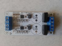
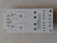
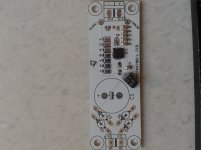
Finally some pictures of "almost finished PCB".
I found this great tutorial how to measure noise, though I still need to source good scope...
Understanding, Measuring, and Reducing Output Voltage Ripple
Best Regards,
Ales
Finally some pictures of "almost finished PCB".
great! I look forward to reading the news!
BTW what do you use to measure noise?
Claudio
I found this great tutorial how to measure noise, though I still need to source good scope...
Understanding, Measuring, and Reducing Output Voltage Ripple
Best Regards,
Ales
Attachments
")
one quick question: what would the recommended maximum current be, in the shown arrangement without external heatsinks?
With or without heatsink maximum output current is 1A. Heatsink on some other designs is, in my opinion, just cosmetics.
BR,
Ales
With or without heatsink maximum output current is 1A. Heatsink on some other designs is, in my opinion, just cosmetics.
BR,
Ales
Yes, the specs don´t change. But depending on the used voltage drop and current drawn, maybe a lot of heat has to dissipate. I assume your PCB´s ground plane is fairly large, so this is not a critical point.
But nevertheless, a heatsink always helps to keep temperatures lower in case of large dissipation...
Florian
The max. current is dependent on the difference between Vin and Vout.
http://www.ti.com/lit/ds/symlink/tps7a4700.pdf
"Dropout Voltage: 307 mV at 1 A"
http://www.ti.com/lit/ds/symlink/tps7a4700.pdf
"Dropout Voltage: 307 mV at 1 A"
The max. current is dependent on the difference between Vin and Vout.
http://www.ti.com/lit/ds/symlink/tps7a4700.pdf
"Dropout Voltage: 307 mV at 1 A"
That figure gives the minimum headroom necessary for currents of 1A. Assuming a high enough headroom, maximum current is always 1A.
The tps7a4700 has an internal thermal protection, which is triggered at 170°C. Basically, it is just necessary to stay under this limit. This depends on the the voltage drop, the current and the heatsinking. As I said, on Ales´boards, there is a large groundplane doing most of the dissipation work.
You can actually estimate the temperature for a given current by taking into account the heat sink area of the PCB with the formulas given in the datasheet.
Bottom side of PCB is completely covered with ground plane. As you can also see I haven't placed any components on the bottom, so heatsink can be applied. Option for heat bridge between PCB and casing is also possible using thermal conductive pads.
I did see that, and it certainly wasn´t meant as criticism. I guess for moderate loads the ground plane will be ok. But if you have heavier loads and large dropout voltage, I assume it would be a nice option to glue on a heatsink, to keep the temperature down. Usually, I use (electrically insulating) thermal-epoxy for making permanent heatsink connections. You can make some really wild constructions with this, so I never thougth this would be a problem...
Ales, could you give me the (estimated) ground pad area in cm^2? If I have the time, maybe I can calculate some estimated temperatures for certain load-situations... Just a thought.
Thanks
Florian
- Status
- This old topic is closed. If you want to reopen this topic, contact a moderator using the "Report Post" button.
- Home
- Amplifiers
- Power Supplies
- Low noise symmetrical PSU TPS7A4701 and TPS7A3301