See whether you can successfully get down to zeta=1 (critical damping) when Cheapomodo is connected to an inductor instead of a transformer. If you don't happen to have a factory made inductor in your parts box, you can still do a quick test with an Improvised Component. Wind 100 turns of insulated wire around an AA battery and use a few wraps of sticky tape to hold the inductor together in one piece when you slide it off the battery. Connect the two ends of the inductor to Cheapomodo's terminal block in place of the transformer. Now see whether you can or can't get the scope waveform you want. It's a boost to your confidence when you see that SOMETHING has been successfully damped.
If your Cheapomodo is working fine and damping inductors well, your problem might be a poor match between the transformer and the trimmer potentiometer. You might need to get another trimmer pot whose total end-to-end resistance is 100 ohms or 50 ohms. This will let you carefully explore the low-resistance region more thoroughly than with a 1K trimmer pot. Maybe you simply had bad luck. Maybe your transformer needs 15 ohms for critical damping, but your 1K pot can only dial down to 25 ohms, not zero (!!?). That would be terrible bad luck but it is not impossible according to Murphy's Law.
If your Cheapomodo is working fine and damping inductors well, your problem might be a poor match between the transformer and the trimmer potentiometer. You might need to get another trimmer pot whose total end-to-end resistance is 100 ohms or 50 ohms. This will let you carefully explore the low-resistance region more thoroughly than with a 1K trimmer pot. Maybe you simply had bad luck. Maybe your transformer needs 15 ohms for critical damping, but your 1K pot can only dial down to 25 ohms, not zero (!!?). That would be terrible bad luck but it is not impossible according to Murphy's Law.
Last edited:
When is overdamped
Hi Mark
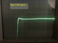
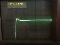
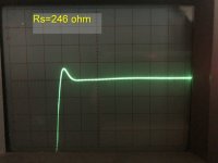
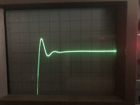
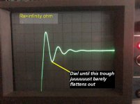
I put together my cheapomodo on a strip board. It's such a great jig. After some figuring out how to use a very old CRT scope, I got the following snubbed images.
For background, my tube preamp (Sonic Frontiers Line3), has 3 transfos: for L, R channels and control circuits.
Each channel transfo has 3 secondary windings, for +240V, -150V and 20V rails. I would think the transfor for each channel is about 60VA-70VA.
I'm using the standard values Cx=.01uF, Cs=.15uF.
My question is when is critically damped and when is overdamped. Seems I can turn the trim pot 50 ohm or more in any direction and the effect is quite small? I fear overdamping may make the SQ sterile. ;(
Denis
PS: the 2nd scope is Rs=713 ohm
Hi Mark
I put together my cheapomodo on a strip board. It's such a great jig. After some figuring out how to use a very old CRT scope, I got the following snubbed images.
For background, my tube preamp (Sonic Frontiers Line3), has 3 transfos: for L, R channels and control circuits.
Each channel transfo has 3 secondary windings, for +240V, -150V and 20V rails. I would think the transfor for each channel is about 60VA-70VA.
I'm using the standard values Cx=.01uF, Cs=.15uF.
My question is when is critically damped and when is overdamped. Seems I can turn the trim pot 50 ohm or more in any direction and the effect is quite small? I fear overdamping may make the SQ sterile. ;(
Denis
PS: the 2nd scope is Rs=713 ohm
Attachments
-
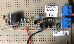 my CheapoModo Circuit Bd.jpg301.3 KB · Views: 311
 -
 B 116 ohm w.jpg87.5 KB · Views: 125
 -
 B 173 ohm w.jpg85.6 KB · Views: 125
 -
 B 246 ohm w.jpg68.7 KB · Views: 125
 -
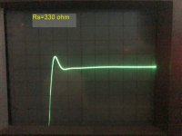 B 330 ohm w.jpg101.4 KB · Views: 304
 -
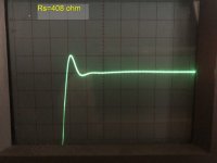 B 408 ohm w.jpg84.1 KB · Views: 319
 -
 B 713 ohm.jpeg694.2 KB · Views: 316
 -
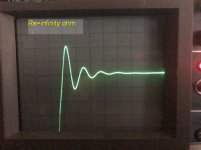 B Infinity ohm w.jpg61.5 KB · Views: 329
Last edited:
Quasimodo posts #1351 and #1358 demonstrate how to calculate the power dissipated in your snubber resistor. I boldly claim, and invite skeptical readers to prove or disprove, that a 1/4 watt resistor is plenty big enough, when:
* secondary voltage = 240 VAC and Rsnub < 550 ohms; OR
* secondary voltage = 150 VAC and Rsnub < 1.6 kohms; OR
* secondary voltage = 20 VAC and Rsnub < 100 kohms
* secondary voltage = 240 VAC and Rsnub < 550 ohms; OR
* secondary voltage = 150 VAC and Rsnub < 1.6 kohms; OR
* secondary voltage = 20 VAC and Rsnub < 100 kohms
I boldly claim, and invite skeptical readers to prove or disprove, that a 1/4 watt resistor is plenty big enough...
Agreed. I read that. Just that Digikey in Canada don't at the moment have lower W resistors at my values and the carbon composits are 5-8x the price.
Learning a lot doing this jig! Thanks Mark.
Effect of not shorting other windings
I have some equipment, especially a 5 channel amp, which is awkward to get at in terms of shorting the other 5 windings when trying to dial in the snubber for 1 winding. So I wondered how usable is the QModo/CModo approach if I did not short out the other windings.
I ran a test with a DAC which has a center tap primary and 3 secondaries: 2 for 6V rails and a center tap winding for the +/-12 Rails. I had already completed determining Rs for each secondary using the correct approach.
For one of the 6V windings, optimum Rs was determined to be ~19R.
I ran new 3 tests scoping this 6V winding.
T1. With primary shorted and only the other 6V winding shorted, but not the +/-12V windings. The scope patterns are very close to that of the correctly shorted procedure and the optimum Rs is also same, ~19R.
T2. With primary shorted but all the other 6V and +/-12V secondary windings NOT shorted. And the outcome is similar to the correctly shorted procedure.
T3. With prim also NOT shorted - i.e. none of the other windings are shorted while applying CModo to a 6V secondary. And the outcome is also very similar to the correctly shorted procedure.
I wonder is this possible? Is my test valid? I am aware that when other winding(s) are not shorted, I am dealing with the inductance of a winding I am probing. And that when other windings are shorted, I am dealing with the probed winding's leakage inductance, which is likely just a low few percent of the winding inductance.
I am baffled, thinking that my test outcome is not possible - but that if not shorting the other windings can yield an approximately OK Rsnubber, then that would be a great time saver.
Any comments please?
Denis
I agree that it is suspicious and not intuitive. I wouldn't draw any firm conclusions from those "experiments".
If you can't test some of the windings, you can't test them. Test the ones you can, snub them correctly, then hope that the others you didn't test, aren't ringing like banshees. I guess you could swap out the diodes and put in super duper soft recovery diodes on the not-measured windings. But without measurement you won't know if this makes a small difference or a big difference.
Linear Audio | your tech audio resource
images
a) Why is it that we are after zeta=1 actually?
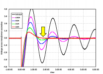
b) The graph still shows overshot, no?

Attachments

Last edited:
Please feel free to adjust the potentiometer on your Cheapomodo, to get whatever waveform shape you like most. No doubt you studied differential equations, Laplace Transforms, and continuous-time control systems on your way to becoming Ing. Michael Gerstgrasser, so you don't need an introductory tutorial on damped oscillation in second order systems.
For those who are not degreed EE's, I recommend a target value of zeta=1.0 (so called "critical damping") because I feel it gives the greatest margin-of-safety against setup errors, measurement errors, and interpretation errors. I lump all of these together into a "beginner's mistakes" category, and I estimate that a beginner's total error can be as large as ±40%. In my opinion, zeta = 1 is the target centerline which gives the least dangerous worst-case, when a beginner accidentally builds (target_zeta ±40%). Zeta=1 also has the secondary benefit of being easy to estimate visually.
For those who ARE degreed EE's: you don't need any advice from me. Pick your own value of zeta based on your own judgement and create your own design. You will probably want to avoid the No-Math approach (since you are very good at math) and perform the calculations instead. In this case you use Cheapomodo simply as a device which measures inductance, extracting L from f_osc data. Figure 17 shows one possible procedure. Then calculate Rdamping from the textbook equation for a second order system
You can view the resulting waveform on your scope, by plugging a resistor whose value is the calculated Rdamping into Cheapomodo. This is a valuable double-check, especially if you are aiming for zeta > 1, because the assumption (Cs is approximately a short circuit) becomes less and less valid as you dial in more and more overdamping. Try it on your own Cheapomodo and observe what happens.
For those who are not degreed EE's, I recommend a target value of zeta=1.0 (so called "critical damping") because I feel it gives the greatest margin-of-safety against setup errors, measurement errors, and interpretation errors. I lump all of these together into a "beginner's mistakes" category, and I estimate that a beginner's total error can be as large as ±40%. In my opinion, zeta = 1 is the target centerline which gives the least dangerous worst-case, when a beginner accidentally builds (target_zeta ±40%). Zeta=1 also has the secondary benefit of being easy to estimate visually.
For those who ARE degreed EE's: you don't need any advice from me. Pick your own value of zeta based on your own judgement and create your own design. You will probably want to avoid the No-Math approach (since you are very good at math) and perform the calculations instead. In this case you use Cheapomodo simply as a device which measures inductance, extracting L from f_osc data. Figure 17 shows one possible procedure. Then calculate Rdamping from the textbook equation for a second order system
- Rdamping = (0.5 / DesiredZeta) * SQRT(L / Ctot)
You can view the resulting waveform on your scope, by plugging a resistor whose value is the calculated Rdamping into Cheapomodo. This is a valuable double-check, especially if you are aiming for zeta > 1, because the assumption (Cs is approximately a short circuit) becomes less and less valid as you dial in more and more overdamping. Try it on your own Cheapomodo and observe what happens.
No need to get any sarcastic!Please feel free to adjust the potentiometer on your Cheapomodo, to get whatever waveform shape you like most. No doubt you studied differential equations, Laplace Transforms, and continuous-time control systems on your way to becoming Ing. Michael Gerstgrasser, so you don't need an introductory tutorial on damped oscillation in second order systems.
And no, I'm not a degreed EE, so no need to get in "Attack is the best means of defence" mode either.
My questions - not really answered, were honest.
They were aimed towards as to why zeta=1 would be any beneficial, say opposed to over damped.
There is so little findings written here about the sonic outcome of the snubberings performed, and I for one would appreciate to get a better handle on the correlation to that.
In the end its not about carrying out an interesting scientists textbook exercise, but to possibly get a step further in terms of sound quality of (modified) audio gear, no?
So I rephrase my questions:
Are there auditioning based observations, that zeta=1 is the sweet spot to go for?
Last edited:
I guess I misunderstood what I read when I clicked the hyperlink in your signature and visited the website "www dot kinotechnik dot edis.at/pages/diyaudio/CMPB/Audio_and_Loudspeaker_Design_Guide_Lines.html" . I saw that it was written by "Ing. Michael Gerstgrasser" and I made
two assumptions: (i) that author is you; (ii) "Ing." means you have a degree in electrical engineering. Apparently my assumptions were not correct and I apologize for the error.
The answer to your question "Why is it that we are after zeta=1 actually?" is
The answer to your question "The graph still shows overshot, no?" is: yes, there is overshoot, but there is no oscillatory ringing.
If you wish more people would post their before-and-after listening evaluations of 2C+1R transformer snubbers, that might turn out to be full of difficulty. How do you motivate or influence other people to do what you want them to do? At first sight it doesn't seem easy, but I wish you good success in the endeavor.
two assumptions: (i) that author is you; (ii) "Ing." means you have a degree in electrical engineering. Apparently my assumptions were not correct and I apologize for the error.
The answer to your question "Why is it that we are after zeta=1 actually?" is
I recommend a target value of zeta=1.0 (so called "critical damping") because I feel it gives the greatest margin-of-safety against setup errors, measurement errors, and interpretation errors. I lump all of these together into a "beginner's mistakes" category, and I estimate that a beginner's total error can be as large as ±40%. In my opinion, zeta = 1 is the target centerline which gives the least dangerous worst-case, when a beginner accidentally builds (target_zeta ±40%). Zeta=1 also has the secondary benefit of being easy to estimate visually.
The answer to your question "The graph still shows overshot, no?" is: yes, there is overshoot, but there is no oscillatory ringing.
If you wish more people would post their before-and-after listening evaluations of 2C+1R transformer snubbers, that might turn out to be full of difficulty. How do you motivate or influence other people to do what you want them to do? At first sight it doesn't seem easy, but I wish you good success in the endeavor.
acceptedApparently my assumptions were not correct and I apologize for the error.
thanks, this part I gotThe answer to your question "Why is it that we are after zeta=1 actually?" is
I recommend a target value of zeta=1.0 (so called "critical damping") because I feel it gives the greatest margin-of-safety against setup errors, measurement errors, and interpretation errors. I lump all of these together into a "beginner's mistakes" category, and I estimate that a beginner's total error can be as large as ±40%. In my opinion, zeta = 1 is the target centerline which gives the least dangerous worst-case, when a beginner accidentally builds (target_zeta ±40%). Zeta=1 also has the secondary benefit of being easy to estimate visually.
Ok, got itThe answer to your question "The graph still shows overshot, no?" is: yes, there is overshoot, but there is no oscillatory ringing.
Well, so much raving about different capacitors making for an improvement in one way or another, same to resistors, opamps and so on, there certainly "should" come up impressions and anecdotal evidence of all sorts.If you wish more people would post their before-and-after listening evaluations of 2C+1R transformer snubbers, that might turn out to be full of difficulty. How do you motivate or influence other people to do what you want them to do? At first sight it doesn't seem easy, but I wish you good success in the endeavor.
Lets wait and see then if it happens and if we possibly can filter out some further useful clues from them.
Thanks for the Qasimodo bell ringer and all the background info you provide!
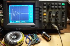
Hello, today my first try on recently completed 'cheapmodo' board, also first use of secondhand osciloscope so... you could figure...
I was in luck after some buttons play, I menage to display the transformer oscilation. See pic. below. The problem I have, is no matter how much I turn the trimmer bolt, there is no change on osciloscope display.
Maybe I miss something
Jordi.
I was in luck after some buttons play, I menage to display the transformer oscilation. See pic. below. The problem I have, is no matter how much I turn the trimmer bolt, there is no change on osciloscope display.
Maybe I miss something
Jordi.
Attachments
Concerning the trimmer, most likely not that, since I already have an spare module (I completed two modules) and no way, both behave the same.
I had already tried that -also to discard bad soldering-
---------------
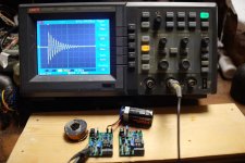
Now I checked an inductor, he has oscilation (see attch) but no way, the 10 turn trimmer from both modules, I turned bolt to the both ends -No way, again not any change in osciloscope display !!
I had already tried that -also to discard bad soldering-
---------------
Now I checked an inductor, he has oscilation (see attch) but no way, the 10 turn trimmer from both modules, I turned bolt to the both ends -No way, again not any change in osciloscope display !!
Attachments
Clearly there is some kind of implementation error on both of your boards, since dozens of other DIYer's here on this thread have successfully built a working Cheapomodo, using the same schematic as you.
Which means you now must begin debugging and troubleshooting, to find out what is wrong with your board(s).
The obvious first thing to check, which I am sure has already occurred to you, and which you have doubtless already tried, is to be sure that all socketed parts are securely plugged into their sockets. Are all three leads of the trimpot securely plugged in? Are both leads of Cs=0.15uF securely plugged in? Are both leads of Cx=0.01uF securely plugged in? Does your DVM show good continuity between the rest of the circuit, and the leads of the socketed components?
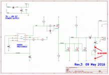
Since the pot seems to do nothing, the next thing to do is to look at the signal waveforms in its vicinity. Luckily one end of the pot is already connected to Ground so you can leave your scope ground clip where it is now. Connect your scope probe to the other end of the pot, as shown below, have Cheapomodo drive an inductor, apply power, and study the trace. When you twirl the knob of the pot, does the trace change? Think about the results, try to imagine what they could mean.
Finally, you probably want to spend 2 hours and duplicate what diyAudio member dwjames did in post #110 of this thread. He built a Cheapomodo on a Solderless Breadboard. Post #110 shows a photo of it. You can do this too, and compare the results against your nonworking PCBs. If your Solderless Breadboard Cheapomodo works, you can use it to snap a picture of the scope trace for every single node in the circuit (there are only ten of them). Which node or nodes are different, between the working Solderless Breadboard Cheapomodo, and the non-working PCB Cheapomodos? That's where your PCB is broken.
_
Which means you now must begin debugging and troubleshooting, to find out what is wrong with your board(s).
The obvious first thing to check, which I am sure has already occurred to you, and which you have doubtless already tried, is to be sure that all socketed parts are securely plugged into their sockets. Are all three leads of the trimpot securely plugged in? Are both leads of Cs=0.15uF securely plugged in? Are both leads of Cx=0.01uF securely plugged in? Does your DVM show good continuity between the rest of the circuit, and the leads of the socketed components?
Since the pot seems to do nothing, the next thing to do is to look at the signal waveforms in its vicinity. Luckily one end of the pot is already connected to Ground so you can leave your scope ground clip where it is now. Connect your scope probe to the other end of the pot, as shown below, have Cheapomodo drive an inductor, apply power, and study the trace. When you twirl the knob of the pot, does the trace change? Think about the results, try to imagine what they could mean.
Finally, you probably want to spend 2 hours and duplicate what diyAudio member dwjames did in post #110 of this thread. He built a Cheapomodo on a Solderless Breadboard. Post #110 shows a photo of it. You can do this too, and compare the results against your nonworking PCBs. If your Solderless Breadboard Cheapomodo works, you can use it to snap a picture of the scope trace for every single node in the circuit (there are only ten of them). Which node or nodes are different, between the working Solderless Breadboard Cheapomodo, and the non-working PCB Cheapomodos? That's where your PCB is broken.
_
Attachments
- Status
- This old topic is closed. If you want to reopen this topic, contact a moderator using the "Report Post" button.
- Home
- Amplifiers
- Power Supplies
- CheapoModo: quick and dirty transformer snubber bellringer jig