Thanks Mark for your reply and unfortunately, for me, your diagnosis was spot on.
I've unsoldered the FETs, which was a pain, with one destroyed in the process, and found 1 faulty and 1 good. I've ordered more FETs and hope they don't go faulty.
I like to try the good FET, so wondered is it OK only having one FET in circuit just for testing purposes.
I've unsoldered the FETs, which was a pain, with one destroyed in the process, and found 1 faulty and 1 good. I've ordered more FETs and hope they don't go faulty.
I like to try the good FET, so wondered is it OK only having one FET in circuit just for testing purposes.
Have now replaced all 3 2N7000 FETs and have produced some results. However, it does not seen to look like these Oscilloscope Outputs
With the oscilloscope set to 1V/div and 10uS/div, these are my results

Overdamped

Underdamped

Critical damping?
Do these results look OK?
With the oscilloscope set to 1V/div and 10uS/div, these are my results
Overdamped
Underdamped
Critical damping?
Do these results look OK?
Do these results look OK?
What does your trace look like with no snubber parts installed in the jig?
You want to set your oscilloscope to trigger on the FALLING edge of the transformer secondary waveform.
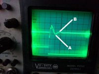
Even better, connect two scope probes to the two channels of the scope: channel A to the transformer secondary, channel B to node "DRAIN" (accessible as the leg of capacitor Cx). Trigger on the falling edge of channel B and display both waveforms on the scope. You should see a dual trace picture very similar to post #85.
Even better, connect two scope probes to the two channels of the scope: channel A to the transformer secondary, channel B to node "DRAIN" (accessible as the leg of capacitor Cx). Trigger on the falling edge of channel B and display both waveforms on the scope. You should see a dual trace picture very similar to post #85.
What does your trace look like with no snubber parts installed in the jig?
With no snubber connected

1V/div 10uS/div

2V/div 10uS/div - Same as above except changed v/div to capture full waveform within display
You want to set your oscilloscope to trigger on the FALLING edge of the transformer secondary waveform.
Even better, connect two scope probes to the two channels of the scope: channel A to the transformer secondary, channel B to node "DRAIN" (accessible as the leg of capacitor Cx). Trigger on the falling edge of channel B and display both waveforms on the scope. You should see a dual trace picture very similar to post #85.
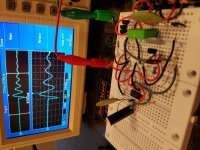
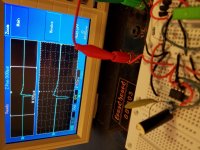
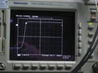
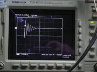
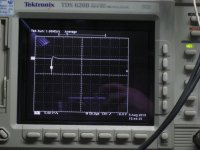
Thanks Mark, did you suggested as seen in the following displays. One peculiar niggle is from the 2nd photo the leading rising edge is jagged and seems to get worse as damping is increased, see 3rd photo. Is this normal bearing in mind I'm using a R-Core transformer.
No damping

Damping

More damping

I've never seen that kind of jaggy edge on any of the Quasimodos I've built and tested, including solderless breadboard, SMD, and thru-hole versions. Not with any of the transformers I've measured.
I've also never seen that kind of jaggy edge on any of the Cheapomodos I've built and tested, including V1-V3, PCB, and stripboard.
I also don't remember ever seeing that kind of jaggy edge on any of the scope photos posted by other DIYA members, either here or in the Quasimodo thread.
Does the jaggy edge disappear when you're driving a fixed inductor instead of the secondary of an R-core transformer? I suspect it's just an artifact of unwanted extra inductance in the ground(s) of your experimental setup. You can move the grounds around, clip the scope ground clip to a different spot, rearrange the positions of the wires, etc., to see what changes and what does not change.
But the good news is, you've almost got the correct Rs dialled in anyway! Dial it down a little more until bump "B" disappears and becomes perfectly flat. Then dial it down a little more after that, very slooooowly, until bump "A" just barely disappears or nearly disappears. Remove the DC power supply from Cheapomodo, measure across Rs with your ohmmeter, done! Disregard, ignore, and pay no attention to the jaggies while you're doing this.
_
Attachments
Thanks for your comment.
This is the R-Core transformer that I bought on Ebay from China. It has 2 secondaries and am testing one at a time.
.jpg")
Interestingly when I join the secondary in series, I get a waveform like yours, without any jaggies. As this method seem more reliable, could I use the derived resistance value for the two snubber circuits used in a centre tapped transformer configuration.
This is the R-Core transformer that I bought on Ebay from China. It has 2 secondaries and am testing one at a time.
Interestingly when I join the secondary in series, I get a waveform like yours, without any jaggies. As this method seem more reliable, could I use the derived resistance value for the two snubber circuits used in a centre tapped transformer configuration.
Just my experience added. Put together the tester circuit on solderless board just to see if I could make it work. It works very well. Will transfer to a soldered board soon. Cx=6800pf and Cs=.1uf. Under test is an Antek AS-1212, a 115/230 - 12-0-12 toroidal.
Great jig Mark.
Great jig Mark.
Attachments
Hello and thank you for providing an easy way to find snuber values !
I am now looking to buy a cheap Scope for DIY audio usage (still quite newbe in the hobby).
I dind't read the full 26 pages but what I noted is the need for min 2uS/div and few other specs. I have a budget of roughly 100€ and so shorted list :
- Owon 1022I
- Bitscope Micro
- PicoScope 2204A
- DSO Nano V3
- DS212
Do you have any recommandation on those ?
Thank you in advance
Last edited:
I've never used any of those scopes myself. Glancing at their sales pages on Amazon, the Owon seems to have the best specifications and that's probably what I'd choose if I were you. It might turn out to be a terrible product, I don't really know, I've never seen or used one. Sorry.
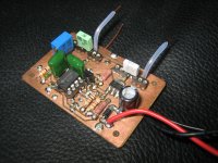
Hot off the press, not tested yet...
But this one was truly made from the parts I has at hand.
I ran out of 0.1uF leaded ceramic caps, substituted with SMD. had no leaded appropriate mosfets.. used an SOT-223 FQT7N10L. As to, R3-900 ohm was substituted with a 1K.
After all this, I made changes to the original design to accept the different parts, and printed it in my kitchen...
Will test it as soon as I have more time, hope it will work...
Very exciting indeed.
Attachments
Last edited:
First, I would like to thank Mark for this wonderful and helpful instrument...
It was powered up today...and IT WORKS..!!
the pictures are:
The test subject is a 12V 30VA transformer.
Step response on R2, no load.
Transformer response, no dampening.
Transformer with the optimized snubber- 150 ohm resistor.
GREAT!!… Thank you very much..
Now I must test to hear if there is a difference in sound ???... will let you know.
Attachments

Hi.
I am a noob on this so please don’t kill me. I have read through the 26 pages and most I didn’t understand. However I think I understood enough to order the components tonight and start trying. My goal is to design the snubber for a 800Va, 230V single prim., 2x25V Amplimo toroid.
When reading through the pages I saw mentioning that the Cheapomodo is like an LC Meter. Was that meant literally? If yes, could I use my existing LC Meter to determine the leakage inductance and with some math derive the values for Cx, Cs and Rs?(I think I even saw an excel sheet here or in a link to the Quasimodo)
Thanks.
Regards
I think you'd benefit from reading post #1 in the Quasimodo thread. Quasimodo is the parent of Cheapomodo. Here's a link:
Simple, no-math transformer snubber using Quasimodo test-jig
In particular, the .pdf attachment which discusses Quasimodo (thus also Cheapomodo) pretty thoroughly Link to Quasimodo manual (.pdf) will be hugely beneficial.
You can slap together a Cheapomodo on a solderless breadboard in about an hour; I recall at least one post in this thread that showed a photograph of somebody's Cheapomodo built this way {aha, there it is, Cheapomodo post #107}. Or you can build it on a little piece of Stripboard / Veroboard, or perfboard, or however you like. You can also have a PCBoard made using the Gerber CAD files I attached a while ago.
One reason why Quasimodo was born, is that I had NO SUCCESS trying to measure transformer leakage inductance using standard test gear. I even measured with an expensive Agilent LCR meter; like everything else I tried, the LCR meter gave inconsistent readings. In my opinion, the reason is that transformer leakage inductance varies with frequency, and so you need to measure it at the resonant frequency of the LRC circuit composed of your transformer, your rectifier(s), and your snubber. The frequency at which it will actually operate. But what the helll is that frequency? I didn't know.
And even if you were somehow able to predict the resonant frequency accurately, then measure leakage inductance at that frequency, you'd still have to use the equations in Hagerman's paper (also found in the Cornell Dubilier application note) to compute component values for your snubber. You'd still have to do mathematics.
Quasimodo and Cheapomodo sidestep all of this busywork by measuring the actual RLC circuit itself, at its resonant frequency, and then visually snubbing resonance away to nothing. Merely by twirling a knob. No LCR meter, no searching around for the correct equations to use, no math. Some people, including myself, don't mind math. But lots and lots of people feel otherwise, and the no-math feature of Quasimodo is quite often the strongest part of its appeal.
By all means, go ahead and try to measure transformer secondary leakage inductance using an LCR meter or other conventional equipment. You'll probably have a lot of fun. Then figure out a way to verify your measurement result: see whether your measured value of inductance, predicts a resonant frequency that matches the actual real-life resonant frequency. To measure resonant frequency, you'll probably end up needing a stimulus/response fixture like Cheapomodo
- Status
- This old topic is closed. If you want to reopen this topic, contact a moderator using the "Report Post" button.
- Home
- Amplifiers
- Power Supplies
- CheapoModo: quick and dirty transformer snubber bellringer jig