A better attempt
The last set of images I posted were taken with Cx mistakenly 1nF instead of 10nF.
These images were taken with Cx=10nF and the results are quite a bit nicer.
It's a 300VA toroid with dual 18V secondaries. The primary and unused secondary are shorted. Rs for a critically damped system = 20ohms
The last set of images I posted were taken with Cx mistakenly 1nF instead of 10nF.
These images were taken with Cx=10nF and the results are quite a bit nicer.
It's a 300VA toroid with dual 18V secondaries. The primary and unused secondary are shorted. Rs for a critically damped system = 20ohms
Attachments
It's a 300VA toroid with dual 18V secondaries. The primary and unused secondary are shorted. Rs for a critically damped system = 20ohms
In operation, the snubber action on one secondary (which is just finishing its conduction phase) occurs when the other secondary is effectively open-circuit (rather than short-circuited as per the standard test jig setup), and the primary winding is connecting to main impedance (rather than short-circuited as per the standard test jig setup).
Merlin el tested the influence on primary termination impedance for his test transformer and couldn't identify any difference in snubber response. Oliphant, are you able to repeat your last test with an open circuit secondary - I'd be guessing it should be similarly negligible for such a toroid.
Ciao, Tim
Tim, what prevents you from assembling a CheapoModo on your own perfboard, and running these tests yourself? Why pester other people to perform your experiments for you?Merlin el tested [a few trials which trobbins requested] ... Oliphant, are you able to repeat your last test with an open circuit secondary
Basically too many other activities with a higher priority and with my workbench full of some part-finished projects - so with this topic I'm stuck being an armchair enthusiast just at the moment. The topic is certainly of interest to many, as it goes to the pursuit of improvement of amp performance, and so it is worthwhile extending the appreciation of why a test is done in some way compared to not in another way, and testing whether that has any impact on the outcome we are all after. It is obvious that the test condition does not 1:1 align with the operating condition the snubber finds itself in an amp, so appreciating better what any difference is would be a worthwhile aim now that the tool itself is quite settled and used by so many.
It so unimportant to you, its priority is so low, that you won't set aside two hours to prototype the jig on a solderless breadboard, and then one more hour to perform the measurements?
It seems that you've been fretting about this for ten months (here's a post from you in Nov 2013), yet you've never spent three hours actually working on it, in all this time? Really?
I think you've demonstrated exactly how (un)important this inquiry actually is.
It seems that you've been fretting about this for ten months (here's a post from you in Nov 2013), yet you've never spent three hours actually working on it, in all this time? Really?
I think you've demonstrated exactly how (un)important this inquiry actually is.
Mark, we all contribute in different ways to a forum, and some of us to many different forums - sometimes we go out of our way to help and assist and generate new material to share with others, or post out items gratis, or help fix others problems gratis - sometimes we don't have that opportunity for a variety of reasons for a particular thread on a particular forum, but can throw a post in here and there. My apologies for not stepping up to the plate on this particular thread.
Oliphant, sorry for not being more precise - merlin el mago was presenting results on the full blown Quasimodo thread
http://www.diyaudio.com/forums/power-supplies/243100-simple-no-math-transformer-snubber-using-quasimodo-test-jig-39.html#post4054668
The mains ac nominally presents 50 ohm impedance to the primary winding for frequencies where a snubber has its impact - this impedance (ie. effectively resistance) was standardised on for conducted EMI test regimes. The 50 ohm ends up in series with the primary winding DCR, and is likely to have little impact on snubber test rig operation compared to using 0 ohm, as indicated by merlin el mago's test transformer results.
Test results from my setup
So I tried various configurations of the transformer and came to two conclusions:
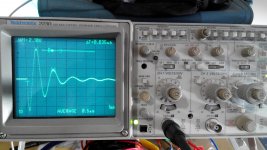
a) There is almost no difference between testing with the primary winding shorted, open or terminated with 50ohms. It had a slightly slower resonance with it open. 1.17MHz compared with 1.2MHz
b) Shorting the other secondary winding cut the resonant frequency almost in half creating a much more sluggish system.
The snubber used was configured as:
Cx = 10nF
Rs = 20ohms
Cs = 100nF
The photos are as follows:
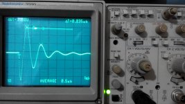
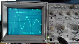
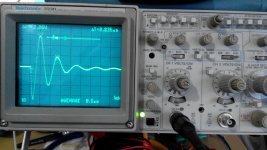
1. Unsnubbed secondary shorted, primary shorted
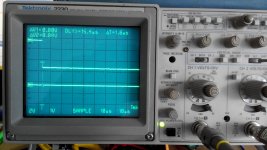
2. Unsnubbed secondary shorted, primary Open
3. Unsnubbed secondary shorted, primary 50ohms
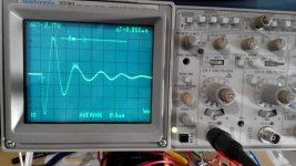
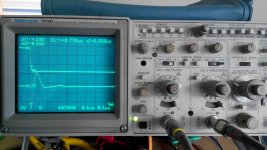
4. Unsnubbed secondary open, primary 50ohms
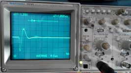
5. Snubbed secondary shorted primary shorted
6. Snubbed secondary shorted primary 50ohms
7. Snubbed secondary open primary 50ohms
Any comments on what is going will be greatly appreciated
So I tried various configurations of the transformer and came to two conclusions:
a) There is almost no difference between testing with the primary winding shorted, open or terminated with 50ohms. It had a slightly slower resonance with it open. 1.17MHz compared with 1.2MHz
b) Shorting the other secondary winding cut the resonant frequency almost in half creating a much more sluggish system.
The snubber used was configured as:
Cx = 10nF
Rs = 20ohms
Cs = 100nF
The photos are as follows:
1. Unsnubbed secondary shorted, primary shorted
2. Unsnubbed secondary shorted, primary Open
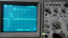
3. Unsnubbed secondary shorted, primary 50ohms
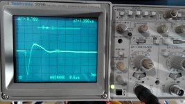
4. Unsnubbed secondary open, primary 50ohms
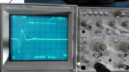
5. Snubbed secondary shorted primary shorted
6. Snubbed secondary shorted primary 50ohms
7. Snubbed secondary open primary 50ohms
Any comments on what is going will be greatly appreciated
Attachments
-
 7 Snubbed 20ohms Sec Sec Open Pri 50ohms.jpg720.1 KB · Views: 239
 -
 6 Snubbed 20ohms Sec Shorted Pri 50ohms.jpg688.8 KB · Views: 215
 -
 5 Snubbed 20ohms Sec Shorted Pri Shorted.jpg728.8 KB · Views: 221
 -
 4 Unsnubbed Sec Open Prim 50ohms.jpg697.8 KB · Views: 198
 -
 3 Unsnubbed Sec Shorted Pri 50ohms.jpg736.6 KB · Views: 778
 -
 2 Unsnubbed Sec Shorted Pri Open.jpg733.8 KB · Views: 798
 -
 1 Unsnubbed Sec Shorted Pri Shorted.jpg714.3 KB · Views: 842
No, it does not..............The mains ac nominally presents 50 ohm impedance to the primary winding for frequencies where a snubber has its impact -..................
The switching pulse on all these recent plots seem very slow.
Normally we see the switching pulse as an almost vertical line on the screen followed by a return and overshoot, with or without ringing.
The pulse is fast, the return and overshoot are slow by comparison.
That's not what we are seeing here.
For comparison post28 shows a FAST pulse, so fast it is invisible on my PC screen.
The return and the ringing are so much slower we can easily see the plots changing in voltage.
Last edited:
Andrew, the design of LISNs for emc measurement are based on early studies of the effective impedance of domestic and industrial mains supplies. A quick google finds books referencing the early papers - I may be able to dig up the LISN design docs I recall reading that went through the justification. 50 ohm is reached in the 100's of kHz, and certainly by 1MHz. The resonances being snubbered are typically likely to be in the 100's of kHz, or higher.
Oliphant, I notice that changes in a shorted primary configuration, such as Mark's example of 115 and 230V configurations in his excellent write up on the Simple .. 'Quasimodo' test jig, haven't changed the resonant frequency of the measured secondary waveform. That suggests to me no change in effective secondary L or C, and only a slight change in R. The change in Mark's example appears to be a change in effective shorting resistance being experienced.
Your plot 2 shows no noticeable impact of a primary with less damping (50 ohm termination or open-circuit).
Your plot 4 for open other secondary shows a lower resonant frequency and less damped, suggesting a change to the other secondary side's effective L and R.
What is the spec of the transformer being tested? (ie. prim volts, secondary volts, DCR's)
Ciao, Tim
Last edited:
Yes, there seems to be a few measurements of mains circuit impedance easily seen on the web.
G.A.Jackson in 1989 'Survey of EMC measurement techniques' has the summary:
"The parameters of the mains network were determined following analysis of many measurements of the RF impedance of mains supplies in household, industrial and other locations. Mean values were found to approximate to an equivalent circuit consisting of 50 ohm in parallel with 50uH. Furthermore, reasonable agreement was found between similar measurements in several countries and so the network was adopted by CISPR and is now specified for RF voltage measurement in many national standards and legal regulations including BS 800 and CISPR Publication 16."
The LISN level is a broad generalisation - and may nowadays be somewhat different if a similar survey was made, given the change in what is connected to the local mains. Luckily, the example measurements so far indicate it has little affect.
I think you mean that opening the other secondary winding reduced the unsnubbed ringing frequency.b) Shorting the other secondary winding cut the resonant frequency almost in half creating a much more sluggish system.
When I compare picture 3 to picture 4 {numbers and names shown in attached screenshot}, I see that the slower ringing is in picture 4, not picture 3. Leaving the other secondary winding open-circuit has apparently cut the ringing frequency.
However I agree with others who worry that the initial transient (step down) looks waaaaay too leisurely. Maybe your use of a single oscilloscope channel is partly responsible; the recommended setup connects channel 1 to node "DRAIN" and channel 2 to node "SCOPE". Trigger on ch1 and display both. (This post) has a photo showing the probes' connections.
If your scope has a square wave "probe calibrator" feature, fiddle with the risetime trimmers in your probe bodies (at the BNC females); maybe they are accidentally set to schmeer_deluxe. On your 100 MHz (Tek 2230) scope+probes, you want risetime/falltime faster than 5 nsec, and a square wave with a perfectly flat top & no ripple.
Attachments

I think you mean that opening the other secondary winding reduced the unsnubbed ringing frequency.
When I compare picture 3 to picture 4 {numbers and names shown in attached screenshot}, I see that the slower ringing is in picture 4, not picture 3. Leaving the other secondary winding open-circuit has apparently cut the ringing frequency.
Ah yes, that was a typo and a rather large one at that. Apologies to those confused by my mistake. When the other secondary was open the ringing frequency was halved.
However I agree with others who worry that the initial transient (step down) looks waaaaay too leisurely. Maybe your use of a single oscilloscope channel is partly responsible; the recommended setup connects channel 1 to node "DRAIN" and channel 2 to node "SCOPE". Trigger on ch1 and display both. (This post) has a photo showing the probes' connections.
Thanks for the guidance Mark I'll try it again later when I'm home and post the results.
The switching pulse on all these recent plots seem very slow.
Normally we see the switching pulse as an almost vertical line on the screen followed by a return and overshoot, with or without ringing.
The pulse is fast, the return and overshoot are slow by comparison.
That's not what we are seeing here.
For comparison post28 shows a FAST pulse, so fast it is invisible on my PC screen.
The return and the ringing are so much slower we can easily see the plots changing in voltage.
In post 28 there's no indication of the Time/Div setting is so it's not an easy thing to make a direct comparison to.
If instead you compare my plots with those produced by Funk1980 in post 15; he has used 10us/Div whereas I used 0.5us/Div.
Compare the difference below (same snubber as in my earlier post #50).
I've connected the probes to the cheapomodo as per Marks post#56.
It could be that my cheapomodo is indeed too slow, but I think a fair comparison is in order before that conclusion is reached.
Attachments
Here is a post showing measured edge rates on Quasimodo v.4. Rise time of the MOSFET gate is about 3 divisions at 10nsec/div. Fall time of the MOSFET drain (i.e. the "SCOPE" node) is about 1/3rd of a division at 10nsec/div. Cheapomodo is naturally expected to be worse, but not 200X worse.
How does the probe+vertical amplifier perform, when you feed it a really snappy square wave from a probe calibrator? The bandwidth - risetime equivalency formula (Wikipedia article here) says that a 100 MHz bandwidth probe+amplifier, ought to be able to display a waveform whose risetime is greater than or equal to 3.5 nanoseconds. Feed in an ideal perfect square wave with 1 picosecond rise time, and the 100 MHz scope+probe will display a 3.5ns risetime.
How does the probe+vertical amplifier perform, when you feed it a really snappy square wave from a probe calibrator? The bandwidth - risetime equivalency formula (Wikipedia article here) says that a 100 MHz bandwidth probe+amplifier, ought to be able to display a waveform whose risetime is greater than or equal to 3.5 nanoseconds. Feed in an ideal perfect square wave with 1 picosecond rise time, and the 100 MHz scope+probe will display a 3.5ns risetime.
Last edited:
Ah yes, that was a typo and a rather large one at that. Apologies to those confused by my mistake. When the other secondary was open the ringing frequency was halved.
Oliphant, my eyeball gauges a resonant frequency reduced to 60%. That indicates a doubling of effective L and C due to the influence of not shorting out the other secondary winding.
If the other secondary winding was the same rating, and closely coupled to the tested winding, then that would make sense, as both windings don't have snubbers on them.
I would profer that a test done on a transformer with a dual secondary used for full-wave rectification (as per typical HV B+ power supply in old valve amps), would best be done with the secondary 'not being tested' to be terminated with the target snubber - as that is the configuration being aimed for. There may be little difference between that non-tested secondary being shorted, and being terminated with a snubber, due to the component values in the snubber. In which case the expeditious use of just a shorted secondary on the other secondary should give a valid result.
Tim
- Status
- This old topic is closed. If you want to reopen this topic, contact a moderator using the "Report Post" button.
- Home
- Amplifiers
- Power Supplies
- CheapoModo: quick and dirty transformer snubber bellringer jig