Very creative, congratulations! It seems the "twin D4184 module" might include a resistor in series with the MOSFET gate, causing a not-so-speedy fall time on the upper trace. This means the hammer you are using to ring the bell, is wrapped in a couple layers of cotton terrycloth, and you're not getting a fast attack BONGG!!! when you smack the bell with the hammer.
I recommend you ALWAYS run a test with the trimpot removed from its socket (thus Rs = infinity), just to verify that the bell is ringing as it should. If so then put back the trimmer and proceed normally. I suggest you do this peace-of-mind verification on every single new transformer winding that you haven't tested before.
I recommend you ALWAYS run a test with the trimpot removed from its socket (thus Rs = infinity), just to verify that the bell is ringing as it should. If so then put back the trimmer and proceed normally. I suggest you do this peace-of-mind verification on every single new transformer winding that you haven't tested before.
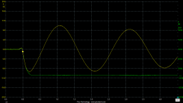
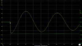
Yep, 100R in the gate on the module (I was being lazy), so as you say the fall time is a bit tardy. If I plot the waveforms together as seen in the first picture, I'm only losing a smallish proportion of the amplitude on excitation. Shorting the resistor for a faster falltime gives the full amplitude as seen in the second picture.Very creative, congratulations! It seems the "twin D4184 module" might include a resistor in series with the MOSFET gate, causing a not-so-speedy fall time on the upper trace. This means the hammer you are using to ring the bell, is wrapped in a couple layers of cotton terrycloth, and you're not getting a fast attack BONGG!!! when you smack the bell with the hammer.
I recommend you ALWAYS run a test with the trimpot removed from its socket (thus Rs = infinity), just to verify that the bell is ringing as it should. If so then put back the trimmer and proceed normally. I suggest you do this peace-of-mind verification on every single new transformer winding that you haven't tested before.
Attachments
Last edited:
Oooh, excellent experimental intuition! I'm impressed, very well done.
Instead of soldering (0R) in parallel with the original (100R), how about going 2/3rds of the way there by soldering (47R) in parallel with (100R)?? That drops you to 32R. Your Arduino drivers are protected if the gate becomes a TOTAL DEAD SHORT but your fall time gets better too.
Instead of soldering (0R) in parallel with the original (100R), how about going 2/3rds of the way there by soldering (47R) in parallel with (100R)?? That drops you to 32R. Your Arduino drivers are protected if the gate becomes a TOTAL DEAD SHORT but your fall time gets better too.
- Status
- This old topic is closed. If you want to reopen this topic, contact a moderator using the "Report Post" button.