Very interesting DS - thanks for bringing that to my attention. Bold of ADI to show noise specs all the way down to 0.1Hz - I've never seen such a well characterized reg, noise-wise.
When low noise supplies are the aim, it pays not to get distracted by impressive noise figures and also take into account load-generated noise which could well be the dominant factor with such a highly specc'd chip. The DS is lacking a Zout vs freq plot - fig22 is the nearest to showing what the Zout looks like (at DC) - a tad over 1mV drop for 100mA out suggests Zout around 10mohms. A 1mA load variation then generates 10uV of noise, swamping that of the reg - remember the Zout will only rise with frequency as all regs look inductive to their load.
<edit> It just dawned on me that another method of getting a handle on the Zout at higher freqs is to examine the load transient plots. For a step change of 0.5A there's a peak deviation around 14mV, suggesting about 30mohms. This will be with the output cap in place presumably, though that's not explicitly stated on the plot.
Last edited:
Nice one ! Too bad it is not solderable by most DIYers.
DIP 8 must come back....
SOIC_N_EP with 1,27mm between legs is not to bad.
When low noise supplies are the aim, it pays not to get distracted by impressive noise figures and also take into account load-generated noise which could well be the dominant factor with such a highly specc'd chip. The DS is lacking a Zout vs freq plot - fig22 is the nearest to showing what the Zout looks like (at DC) - a tad over 1mV drop for 100mA out suggests Zout around 10mohms. A 1mA load variation then generates 10uV of noise, swamping that of the reg - remember the Zout will only rise with frequency as all regs look inductive to their load.
Thanks to point it out. I've never thought about the influence of Z. By the way, I'm glad it draws some pro's attention here. Maybe I will read some reviews soon.
This is some interesting feedback...Thanks for a different perspective.
The output Z isn't really something we thought about when we designed this part. DC load regulation was our primary focus not necessarily AC output Z. This is primarily targeted at RF applications which have fairly static load profiles and the output capacitance handles the >10MHz small signal transients. Even so, the LDO error amp has a unity gain bandwidth of about 20MHz and the open loop gain is at least 60dB up to 20KHz. With this much negative feedback, the output Z is greatly reduced from DC to over 100KHz.
I suspect that the output impedance is lower than the 500mA load transient response might indicate as Fig 45 shows a large signal transient response. The load step is approximately 1.25A/uS which translates to a power bandwidth of about 400KHz for a 500mA peak to peak swing. I think the output Z most people are interested in is really a small signal issue. I can't imagine an audio preamp requiring a power bandwidth of 400KHz, at least not with a load swing of 500mA.
I'll look into having some simulations done to see what the actual small signal AC output impedance looks like. I may try to look at it in the lab depending on what the simulation shows.
Another factor almost everyone seems to ignore is that the Power Supply Rejection Ratio (PSRR) of the regulator is every bit as important and the output voltage noise. You can have a very quiet regulator when it is powered by batteries but is totally noisy when powered from an AC source. If you have only 60dB of PSRR and have 1mV of noise on the regulator supply, the resultant noise due to the sources is 1uV. Many LDOs struggle to achieve 60dB of PSRR at 100KHz when they are loaded near their maximum rating.
Also, sorry about the lack of leaded packages for all you DIY'ers. I guess you'll have to make do with the SOIC.
Hi all,
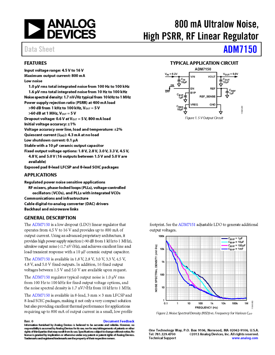
The designer of the ADM7150 was kind enough to run some simulations of the ADM7150 output impedance for several load cases. I've attached the simulations results to this response. As can be seen in the simulations, the output Z of the ADM7150 is well under 1 milli-ohm up to 3KHz smoothly and rises to about 18 milli-ohms at 100KHz. The output Z is somewhat load dependent, especially below 1KHz, because the open loop gain of the LDO is load dependent.
There may some confusion about the difference between these simulations and the test data shown in the datasheet figures. The simulations assume a 1 milli-ohm interconnect resistance while the actual part under test probably had 5 to 10 milli-ohm PC board resistance between the LDO output pin and where the output voltage was measured.
When the native output Z of an LDO is so low, the interconnect resistance can dominate to output Z, and therefore load induced noise, of the total system. Great care must be taken to keep impedances as low as possible if the best possible performance is to be attained.
Attachments
Hi gmorita, you may wish to strike up a conversation with diyAudio member "jackinnj", who published a huge study of measurements AND listening tests on voltage regulators, in Linear Audio magazine volume 4. His most recent data suggests that the best correlation between subjective listening pleasure, and electrical measurement results, comes from the following test:
Connect the signal generator of an AP System Two distortion tester, so that it drives the LOAD of the voltage regulator {Iout = 50mA * (1 + sin(jwt)}. Measure the THD of the output voltage, as a function of frequency. When the load current is a 1kHz pure sinewave, does the regulator produce (unwanted!) harmonics at 2kHz, 3kHz, 4kHz, etc? What is the structure of these harmonics?
So far the clear winner [best measurements, best sonic evaluation] has been an opamp + external BJT pass transistor, a la Walt Jung. For the opamp, Jack observes that high gain at DC gives better scores, high GBWP gives much better scores.
Last edited:
Very interesting part, not prehaps so much for audio, but for those of us doing precision rf (including such things as clocks and DDS boards where there is a well known issue with psu noise -> PN conversion) these could be very cool.
Are any of the usual suspects carrying this part?
I have a direct digital down conversion application where this part looks like an excellent contender for the ADCs, and PLL supplies, but Farnelll, Digikey, Mouser do not seem to carry the parts.
Regards, Dan.
Are any of the usual suspects carrying this part?
I have a direct digital down conversion application where this part looks like an excellent contender for the ADCs, and PLL supplies, but Farnelll, Digikey, Mouser do not seem to carry the parts.
Regards, Dan.
Thanks for the very useful input ") I fully take your point about the load transient plots telling the large signal story whereas we're really interested in the small signal condition. I was rather clutching at straws in getting a handle on the missing info about Zout.
I fully take your point about the load transient plots telling the large signal story whereas we're really interested in the small signal condition. I was rather clutching at straws in getting a handle on the missing info about Zout.
When it comes to how regulators sound there's a lot of heat generated on forums, but not much light. My own perspective is that perhaps how the regulator responds to wideband noise imposed on its output has a lot to do with it. I realize that ADI's not going to sell very many regs into the 'audiophile' business when compared to mobile comms, but I was rather wondering if you could cajole the designer into running a sim for us all here akin to a MTPR (like you have on AD8016 and AD8017) test?
Just to put some meat on the bones for why this is interesting. Audio performance is about getting low IMD with very complex signals (music) which, from the point of view of measurements, most correspond to the multitone signals used to test ADSL drivers. When such a signal is fed to a loaded classB output stage a half-wave rectified version of that signal appears on the power rail - extending its bandwidth beyond the audio range.
I have a hunch that if the IMD performance of the regulator's less than stellar it will respond to that wideband noise by generating its own noise. Would it be possible to run such a simulation and show us the results here?
I fully take your point about the load transient plots telling the large signal story whereas we're really interested in the small signal condition. I was rather clutching at straws in getting a handle on the missing info about Zout.When it comes to how regulators sound there's a lot of heat generated on forums, but not much light. My own perspective is that perhaps how the regulator responds to wideband noise imposed on its output has a lot to do with it. I realize that ADI's not going to sell very many regs into the 'audiophile' business when compared to mobile comms, but I was rather wondering if you could cajole the designer into running a sim for us all here akin to a MTPR (like you have on AD8016 and AD8017) test?
Just to put some meat on the bones for why this is interesting. Audio performance is about getting low IMD with very complex signals (music) which, from the point of view of measurements, most correspond to the multitone signals used to test ADSL drivers. When such a signal is fed to a loaded classB output stage a half-wave rectified version of that signal appears on the power rail - extending its bandwidth beyond the audio range.
I have a hunch that if the IMD performance of the regulator's less than stellar it will respond to that wideband noise by generating its own noise. Would it be possible to run such a simulation and show us the results here?
dmills said:I have a direct digital down conversion application where this part looks like an excellent contender for the ADCs, and PLL supplies, but Farnelll, Digikey, Mouser do not seem to carry the parts.
DigiKey can draw from Factory Stock if their website can be trusted
Hi all,
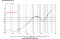
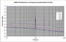
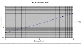
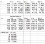
I've been able to get some simulations for the THD of the ADM7150 for different excitation currents at 1KHz. The attached tables below shows how may dB down the harmonics are from the 1KHz fundamental.
I'd like to know what you all feel is a reasonble level of distorion for a power supply.
I've been able to get some simulations for the THD of the ADM7150 for different excitation currents at 1KHz. The attached tables below shows how may dB down the harmonics are from the 1KHz fundamental.
I'd like to know what you all feel is a reasonble level of distorion for a power supply.
Attachments
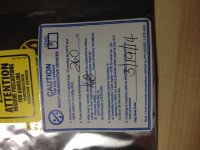

The storage requirement for low humidity is to prevent moisture from entering the device package and causing the part to crack when it is sent through a re-flow oven for soldering.
If you are planning to hand solder or re-flow the ADM7150 on a hot plate, I recommend pre-heating the part for several minutes to ensure that any moisture is driven out of the package.
If you are planning to hand solder or re-flow the ADM7150 on a hot plate, I recommend pre-heating the part for several minutes to ensure that any moisture is driven out of the package.
There are no plans to make an LM317 pin compatible version since the ADM7150 requires 5 capacitors for proper operation.
Baking the parts at 125C for at least 10 to 15 minutes should suffice in driving out most of the moisture. Obviously, the longer the bake the more moisture is driven out.
If the parts have been exposed to room humidity for a long time, say over 1 month, bake times longer than 15 minutes will be required.
If the parts are used immediately after being removed from their packaging, baking will not be necessary.
The PCB in my mind should incorporate spaces for the capacitors and in the size of TO-220 (perhaps taller but not wider) therefore enabling the component for direct replacement of 78xx and 317 series. This would be very convenient.
Just curious about the necessity to bake the component. If the component is soldered to a circuit and the circuit was being left in room humidity for months without turning on, what would happen?
Just curious about the necessity to bake the component. If the component is soldered to a circuit and the circuit was being left in room humidity for months without turning on, what would happen?
It's only necessary to bake the parts prior to initial assembly. After that, the normal operating temperature won't exceed 125C.
Interesting idea about a circuit board. The one difficulty is that the tab of the TO-220 is electrically connected to the output. The ADM7150 exposed pad is connected to ground.
Interesting idea about a circuit board. The one difficulty is that the tab of the TO-220 is electrically connected to the output. The ADM7150 exposed pad is connected to ground.
Are any of the usual suspects carrying this part? .
mouser
- Status
- This old topic is closed. If you want to reopen this topic, contact a moderator using the "Report Post" button.
- Home
- Amplifiers
- Power Supplies
- Modern ultra low noise LDO - ADM7150