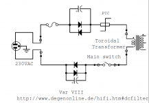
will this work as effective as brystons?
Secondly im thinking that would there be chance if there is mains dc filter is not used for common mode chokes. If there is DC any choke will get saturated. If you look at one positive cycle with dc in it im sure the common mode choke will get saturated. I strongly feel dc blocking to be done before the the common mode and differential mode chokes.
I have a doubt that would that really be the case as core saturation in cm chokes?
secondly if so there are two windings in cm chokes. so we need two filters one for phase and one for neutral. If so can we use two bryston style filters?
Attachments
If "PTC" means "Positive Temperature Coefficient", that appears to be incorrect.
0.2 ohms at room temperature but 20 ohms at 90 degrees C, is exactly what I do not want.
I want high resistance at room temperature (i.e. before power is applied), gradually falling to very low resistance as the unit heats up (i.e. long after power is applied). The current is low at power on, because it is limited by the high series resistance. The current gradually rises because the series resistance gradually falls. So what I want is a "NTC" (Negative Temperature Coefficient) resistance element in series with the primary of my transformer.
My Amplimo 500VA transformer is buzzing slightly, even without load. I found this thread only yesterday, and I'm wondering what is a reliable way of testing the (230 Volts) mains for any DC? Just testing with my DMM in DC mode shows 0 Volts, but is this reliable?
Regards, Gerrit
Regards, Gerrit
Don't try to do any measurements for DC on the mains. You require a special set up becasue a DVM won't handle it.
If the transformer has a constant hum then it's not likely that it's DC on the mains since the DC normally is varying and by this also a varying hum.
But you can always try with a DC filter to see if you will get any improvement.
If the transformer has a constant hum then it's not likely that it's DC on the mains since the DC normally is varying and by this also a varying hum.
But you can always try with a DC filter to see if you will get any improvement.
On September and October 2015 I wrote two articles about the dc over ac.
In attach there is a little test set to measure the dc.
One resistor and two cap. The Ft is 0,05 Hz.
You can measure with tester in dc the voltage dc ( if present) on the ends of the cap.
In the photo the dc value on the trafo under test.
I sent a disturb trough the hair dryer at half power, in this case a diode is put in series with the resistance of the stuff.
This is the simply way to get the dc over ac
Walter
Attachments


Last edited:
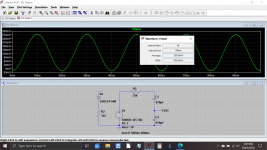
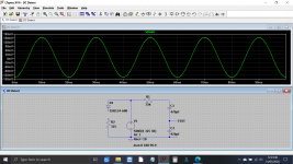
An interesting one to simulate...
I'll let you guys interpret the result") The voltage source has 10 ohms series resistance so that the diode load can introduce the required distortion.
The voltage source has 10 ohms series resistance so that the diode load can introduce the required distortion.
With no load there is a hmmm... offset. Not quite sure why that is so tbh.
A one amp peak load changes the result.
I'll let you guys interpret the result
The voltage source has 10 ohms series resistance so that the diode load can introduce the required distortion.With no load there is a hmmm... offset. Not quite sure why that is so tbh.
A one amp peak load changes the result.
Attachments
Isolation transformers aren't just used for 'safe testing' applications. In your situation, an isolation transformer can be used to indicate if 'dc' on the mains is, or is not, the issue with your hum/buzz.I don’t have one, for safe testing I use a variac.
Regards, Gerrit
to mooly,
your circut is not right.
Check the one I sent
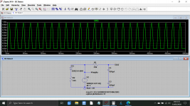
In attach the basic circuit to get the dc over ac.
It is a simply one; it is in italian but easy to undersyand.
The "elemento" is the resistive load of the hair dryer.
When the switch is on "metà potenza" the power goes to 1 kw from 2 kw and the dc (impulsive) comes on
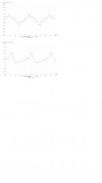
On second picture there are the diagrams of the current that flows on a Rx acting as test point ( with a differential probe)
On top the current without disturb
On bottom with disturb, the negative part is partially gone
Walter
your circut is not right.
Check the one I sent
In attach the basic circuit to get the dc over ac.
It is a simply one; it is in italian but easy to undersyand.
The "elemento" is the resistive load of the hair dryer.
When the switch is on "metà potenza" the power goes to 1 kw from 2 kw and the dc (impulsive) comes on
On second picture there are the diagrams of the current that flows on a Rx acting as test point ( with a differential probe)
On top the current without disturb
On bottom with disturb, the negative part is partially gone
Walter
Attachments

Thanks Walter
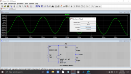
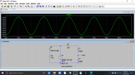
I can't see an error in the simulation circuit but did find the reason for it not showing an offset... I wasn't running the sim for long enough.
This shows the same simulation but running longer. 1 amp peak load as before in the second shot.
I can't see an error in the simulation circuit but did find the reason for it not showing an offset... I wasn't running the sim for long enough.
This shows the same simulation but running longer. 1 amp peak load as before in the second shot.
Attachments
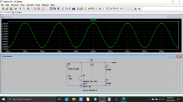
The reactance of the caps is now 14 ohm ( around) at 50Hz.
With maths at TEST point I have around 0,3 vac rms, and 0,846 vpk that is the value you have
IF:
vac is 325 volt , the freq. is 50 Hz.
Of course a residual of 50Hz is present.
You can also look at the symmetry of wave; with dc one half has a different value of the other.
try to put 32 ohm instead of 325 ohm after the diode.
The disturb is not strong
Normally, when the 220vac is involved with dc. the reason comes otuside home and it is propagated
PS= in your previous circuit the value is exactly the half of the last one.
Walter
Last edited:
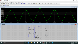
I set the voltage at 325 because that signifies the peak in the simulation, the rms value is 230 volts.
Because the voltage source in simulation is 'perfect' I added a series resistance internal to the supply of 10 ohms. That allows the diode load to cause asymmetry in the supply voltage. 32 ohm would draw over 10 amps peak
These shots show the purity of the driving source. The diode and its 325 ohm load (so around 1 amp peak) cause very obvious distortion (mainly even harmonic as expected) and this asymmetry is what I think we call 'DC on the mains'. It is a shift in the average value (which should be zero) caused by the asymmetry of the waveform.
Also shown is the diode current.
The results were twice the previous value because the equal value caps effectively formed a potential divider at AC and so each cap would see half the voltage.
Attachments
Last edited:
I use for thest a load of 2kw (full) or 1kw switched as diagram I sent ( the disturb ).
In this way the value of dc read is more than 3 volt, as on picture with tester.
This allowed me to test some power trafo to understand if the efficency ( this is what we are speaking) is fine or not.
3 volt with a primary dc resistance of 30 ohm, it is an example, give 100 mA of current tha is not so little.
In some case, trafo with EI iron and a good toro, nothing happen at the power circuit that supply voltage.
In other case, poor toro mainly, some voltage change but nothing important.
The main problem is with the toroidal trafo where the quality of the iron + the winding is poor.
Someone, to save money ( and space), calculate the trafo giving a high vaule of induction.
So when we have the asymmetry on ac (= dc voltage) the noise can appaer.
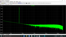
I have also traced the FFT of ac without and with disturb and, in the real world, is different form simulation this because the ac is not pure, of course; normally the even harmonics are present.
With the disturb the odd come out heavily.
With simulation can you read the dc voltage at the test point?
ps= maybe the definition dc over ac is not properly right
Walter
In this way the value of dc read is more than 3 volt, as on picture with tester.
This allowed me to test some power trafo to understand if the efficency ( this is what we are speaking) is fine or not.
3 volt with a primary dc resistance of 30 ohm, it is an example, give 100 mA of current tha is not so little.
In some case, trafo with EI iron and a good toro, nothing happen at the power circuit that supply voltage.
In other case, poor toro mainly, some voltage change but nothing important.
The main problem is with the toroidal trafo where the quality of the iron + the winding is poor.
Someone, to save money ( and space), calculate the trafo giving a high vaule of induction.
So when we have the asymmetry on ac (= dc voltage) the noise can appaer.
I have also traced the FFT of ac without and with disturb and, in the real world, is different form simulation this because the ac is not pure, of course; normally the even harmonics are present.
With the disturb the odd come out heavily.
With simulation can you read the dc voltage at the test point?
ps= maybe the definition dc over ac is not properly right
Walter
- Status
- This old topic is closed. If you want to reopen this topic, contact a moderator using the "Report Post" button.
- Home
- Amplifiers
- Power Supplies
- DC blockers and mains filters