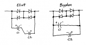
In Elliot's recommended config, the capacitors are in series and polarity reversed.
During a mains half-cycle, as the voltage across the blocker rises and approaches the series diode conduction level, then it may be that the reverse biased cap starts to become non-ideal, with an effective parallel resistance forming across the capacitance (ie. leakage increases with the dynamic half-cycle reverse bias voltage). The other cap is 'normal' during that half-cycle.
If that non-ideal capacitor characteristic occurred, then the mid-point voltage of the caps would deviate from the mid-point voltage of the diodes. As such, a voltage would develop across any 'link resistor'.
I doubt any spice capacitance model includes electrolytic reverse bias modelling?
If that effect did occur, then it would be measurable as a twice mains frequency voltage across the link resistor. In Elliot's config, the peak reverse capacitor voltage is that of a conducting diode junction voltage. If the reverse biased cap did starting conducting resistive leakage current in addition to capacitive current, then its terminal voltage would start reducing and hence suppress the reverse voltage level. Adding a link resistor may negate that suppressed voltage (ie. worse for the reverse biased cap).
Last edited:
Now place a shorting bar across D1 and another shorting bar across D5. Hmmm.
I would assume it reduces the available range of DC that can be blocked.
Hmmm... I suppose it would
")
In Elliot's recommended config, the capacitors are in series and polarity reversed. ...................
I doubt any spice capacitance model includes electrolytic reverse bias modelling?
The 'proof' of any of these circuits has to be.
1/ Do they work, and do they substantially quieten a noisy toroid.
2/ Do they continue to work correctly after say 5 or 10 years and when tested under the same conditions.
These two points can not be modelled in simulation.
I don't know. Do they know?If my solution gives you a long life time and it removes DC, why do want to add more parts?
These two points can not be modelled in simulation.
Well we could wait 10 years for at least 10 examples to be used consistently, and have another 10 examples in a circuit applying nearly the same conditions but with no applied reverse bias, and then someone could put the electrolytics through a parameter test and then try and tease out whether any conclusions can be made. Is that the form of proof you were after?
We could also test the operation of the circuit now (in a safe manner) where the electrolytic voltages were measured to see when non-ideal behaviour started to occur. The test jigs could be (a) a schottky bridge, (b) a pn bridge, (c) a circuit with twice the series pn diodes, (d) a circuit with 3x the series diodes. And apply conditions where the diodes were just starting to conduct so that the reverse bias stress on the caps is worst. If the caps don't exhibit non-ideal behaviour for up to some peak reverse voltage then that would be a good indication of future 'proof'.
Perhaps a single e-cap could be tested in a simpler jig to identify the non-ideal characteristic, and hence provide confidence that the caps are not being stressed in a particular circuit arrangement.
Is that the form of proof you were after?
Its as good as any.
All the design and research put into products doesn't necessarily guarantee they work as intended when used out in the field. Electronics, cars you name it... the problems in a design appear when the average user gets their hands on it.
The best generic info I can easily locate on reverse voltage performance of e-caps is in the following links. There is nothing there to suggest that up to -0.7Vpk, with a low duty cycle, is going to materially affect the service life. Especially if the capacitance is such that normal operating voltage swing is < 0.7Vpk.
Its plausible that a fault level current through the diodes could expose a cap to a transient reverse voltage in the range 1-1.5V. The series forward biased capacitor should limit current through the caps, so I can see an inherent safety mechanism.
http://www.mouser.com/pdfDocs/UCC_ElectrolyticCapacitorTechnicalNotes.pdf
Product Information: Aluminum Electrolytic Capacitors FAQ/Capacitor, Power Supply Units RUBYCON CORPORATION
I have sold many DC blockers and they are the; retro-thermionic "DC Duffer". Many have told me they have a power conditioner and I explain to them that power conditioners do not block DC. The isolated and quazi conditioner above will be strongly effected and degraded by DC which exists on all power lines. The first "isolation" transformers inductive qualities will be heavily reduced by the DC on the mains. It will probably function at 60% of its theoretical max. Therefore everything, yes everything down stream is now hobbled by this power conditioner.Just for fun, a useful circuit. The way to test it is to reverse the AC plug and see if the output voltage swings the other way to the same value. You might have to adjust the RC values depending on your meter and transformer.
To calibrate it use a two diodes in series with one anti-parallel. The whole thing in series with the AC line.
Mark you can use any diode of your choice.
If you do not have a DC blocker as the first item from your power outlet every item of your gear will never function to its full caperbilities. The worse effected are anything which has a toriod power transformer. Commercial power amp which use toriod transformers us them because they are cheap. They are cheap because there is no or very little iron in them. These trannies are manufactured cheaply because iron is expensive and heavy. If you are going to ship power amps OS make them light and use toriods. Toriods hum and buzz however when there is DC on the line.
Much, much worse than that there effectiveness as EMI/RFI filters is greatly reduced. Your music quality will always by effected in this case. IE trannies do not suffer as badly because there is a lot more iron and fortunately thier abilities to filter crud from mains is far more effective. Down side is they are heavier and with more iron, more expensive. Also stray mag. fields have to be considered when using them. Ever wondered why tubes amps sound so good. Take a look at thier power trannies and chokes - lots of iron.
Get a DC blocker and enjoy your music more. I did and I am.
Peranders, I can't find your solution; which post# contains it? Are you speaking about post#151?If my solution gives you a long life time and it removes DC, why do want to add more parts?
Those who wish to orate and lecture about long term reliability of mains DC blockers, are invited to study the giant trove of product schematics on Bryston's website. As far as I am aware, Bryston has earned its steller reputation as a builder of high quality and reliable equipment which lasts for decades.
When you view their schematics, you'll see that Bryston disregard's Rod Elliott's advice to make nonpolar capacitor structures by placing two polar electrolytic capacitors in series. Bryston simply connects their capacitors straight across the mains blocker terminals. Theoretically this could place as much as (2 x Vfwd) volts of reverse bias across each capacitor, where Vfwd is the forward voltage drop of the diodes in the bridge rectifier. And yet, Bryston's products don't seem to fail, in real world use, in the field.
Lecture away!
_
Attachments
Im thinking of putting a filter in my f4 with the slow start board.
I think ive narrowed it down to schaffner fn2090.
They do 3 versions but i can only find 2.
One (vanilla, non A or B version) has Y caps and has leakage of 0.67mA (the farnell site says 0.67uA but im going with the data sheet here!)
and a medical (B) version that has no Y caps but much lower leakage 0.002mA
Any idea what would would suit better?
Im using a 500va transformer so I would think that a 6amp versions would be plenty although if i go for the low leakage version they only have the 10A.
I looked at the data sheets for a load of there filters and these seem to have very attenuation.
http://www.farnell.com/datasheets/1563468.pdf?_ga=1.95759324.1120660167.1452175866
You don't mention a safety need associated with "medical", therefore I suggest you use the non medical version that includes the Y caps and has better interference attenuation.
500VA is only a tiny bit over 2Aac. Therefore I'd choose between 1A and 3A for a mains filter since the 500VA will rarely operate at near maximum power.
500VA is only a tiny bit over 2Aac. Therefore I'd choose between 1A and 3A for a mains filter since the 500VA will rarely operate at near maximum power.
Last edited:
Hello everyone. I have read through this thread and several similar ones so I was looking for some advice regarding transformer hum with my audio gear. My ring main has loads of switching power supplies, a large computer and the kitchen on it so my mains quality is very low. I suspect this is causing issue with my audio equipment transformers so I wanted to get a DC Blocker with RFI filters.
However I don't really have any experience making mains power electronics so I was looking for somewhere in the UK that will sell them preferably without the insane inflated prices of MCRU as £450 for the required components seems like a massive ripoff. I have tried for a couple of weeks to find somewhere and the only place I found won't reply to my emails (Tomanek in Poland). Any help would be greatly appreciated.
However I don't really have any experience making mains power electronics so I was looking for somewhere in the UK that will sell them preferably without the insane inflated prices of MCRU as £450 for the required components seems like a massive ripoff. I have tried for a couple of weeks to find somewhere and the only place I found won't reply to my emails (Tomanek in Poland). Any help would be greatly appreciated.
A DC blocker (PCB or assembled) can be bought from Peranders.
Or assemble yourself from a some low voltage electrolytics and some 1n5402 (or higher)
An IEC input socket with an integrated filter can be bought in 1A, 2A, 3A or 6A versions.
You can buy these with an integrated fuse holder.
You can also buy one with a switch, but I find that superfluous, easier to pull the plug out.
A DC blocker (PCB or assembled) can be bought from Peranders.
Or assemble yourself from a some low voltage electrolytics and some 1n5402 (or higher)
An IEC input socket with an integrated filter can be bought in 1A, 2A, 3A or 6A versions.
You can buy these with an integrated fuse holder.
You can also buy one with a switch, but I find that superfluous, easier to pull the plug out.
Thanks for the information, I will throw them an email
- Status
- This old topic is closed. If you want to reopen this topic, contact a moderator using the "Report Post" button.
- Home
- Amplifiers
- Power Supplies
- DC blockers and mains filters