Hi
Hopefully this little project by a novice is worthy of your attention and assistance!
I have assembled an audio server made up with an ASRock Z87E-ITX mobo, Haswell 4570T processor, ESI Juli@ XTe sound card with clocks upgraded with a Fidelity Audio Micro Clock 2 and PicoPSU power supply with 12V 'brick'.
In the interest of achieving a better power supply and learning more about electronics I have been upgrading the power supply. As a first step, and with a lot of kind assistance from Brent of Fidelity Audio here in the UK, I assembled with point-to-point wiring a 12V 'rail' comprising two 22,000uF Fidelity Audio 'SI' caps, an SPower HC 12v regulator and another 22,000uF 'SI' capacitor, fed 18V from another 'brick'. The caps and regulator may well be overkill for this application but it seems to work very well. This 12V powers the PicoPSU and the Micro Clock 2.
I'm interested in taking this a step or two further. One direction, although it may not be the first one that I implement, is to replace the brick with a 160VA toroidal transformer with 15V secondaries and a full-wave bridge rectifier made from four Cree C3D08060A Silicon Carbide Schottky diodes. 160VA may well be more than enough but it fits.
The second direction involves what I believe is a CLC filter. Specifically, it has been suggested to me that my existing setup could be improved further by adding a series of film capacitors and a choke ahead of the 'SI' caps:
Input
Wima MKP10 0.47uF 1600V
Wima MKP10 0.047uF 1000V
Wima MKP10 4700pF 1000V
Coilcraft CMT4 26mH 6A 0.115Ohm
Existing caps...etc
I picked up these parts (I got the choke cheekily as a request for sample and the Wima caps were essentially free as they tipped my Mouser order into free delivery) but as I read a bit more about CLC filters I'm unsure that these cap values are appropriate for this application or indeed whether the filter adds anything beyond the existing cap/regulator setup. (The choke is, ahem, huge but can be made to fit.)
I'd therefore like to start by asking for thoughts on the filter, both with respect to adding it into my existing 'brick' setup and with respect to the transformer/rectifier setup.
I'm sure I will have questions on the transformer/rectifier as well at some point.
Thanks in advance
Steve
Last edited:
I suggest that an excellent application of the next ~ €239 of your DIY budget, would be to purchase an oscilloscope with probes. Then you can view the voltage waveforms at the various nodes in your existing power supply, to see how well or poorly it is performing. You can also discover anomalies due to poor ground layout and/or inefficient go-and-return loop wiring. You can study the amount of ripple, and watch as it decreases (or fails to decrease!) as you march your probe from the transformer to the output. You can study noise and compare against theoretical predictions from ideal lowpass filter equations.
Finally, as { diyAudio member zigzagflux } points out, when you have an oscilloscope, you can use it to dial in an optimum snubber, which completely damps any possibility of transformer secondary ringing.
Finally, as { diyAudio member zigzagflux } points out, when you have an oscilloscope, you can use it to dial in an optimum snubber, which completely damps any possibility of transformer secondary ringing.
Thanks for the response! I guess I might have seen that one coming. ") In the immediate short term, I can likely borrow one from a good friend and learn a little about how to use it - assuming I can get him interested in my project (he is relatively new to electronics but has made the investment you recommend).
In the immediate short term, I can likely borrow one from a good friend and learn a little about how to use it - assuming I can get him interested in my project (he is relatively new to electronics but has made the investment you recommend).
As I read and tried to absorb the discussion in the snubber thread and your Quasimodo thread (and the material you linked to) I was thinking the issue of transformer secondary ringing and tackling that with an optimum snubber was not necessarily the same thing as what the CLC filter which was proposed to me (as described above) or rather that these were separate issues (as separate as things can be in electronics). Is wrong?
I suspect you would tell me to get the toroid and rectifier up and running and then work on optimising that setup as I learn more rather than trying to improve on a brick DC input which will ultimately be replaced. To that end, can I check that I have properly interpreted the pin configuration of the Cree diodes into an actual wiring diagram for the rectifier? Apologies for the corny graphic!
Thanks again
Steve
In the immediate short term, I can likely borrow one from a good friend and learn a little about how to use it - assuming I can get him interested in my project (he is relatively new to electronics but has made the investment you recommend). As I read and tried to absorb the discussion in the snubber thread and your Quasimodo thread (and the material you linked to) I was thinking the issue of transformer secondary ringing and tackling that with an optimum snubber was not necessarily the same thing as what the CLC filter which was proposed to me (as described above) or rather that these were separate issues (as separate as things can be in electronics). Is wrong?
I suspect you would tell me to get the toroid and rectifier up and running and then work on optimising that setup as I learn more rather than trying to improve on a brick DC input which will ultimately be replaced. To that end, can I check that I have properly interpreted the pin configuration of the Cree diodes into an actual wiring diagram for the rectifier? Apologies for the corny graphic!
An externally hosted image should be here but it was not working when we last tested it.
Thanks again
Steve
Last edited:
Your drawing looks correct except the ~L wire is labeled "A" at lower right. Also notice that the case of each diode is electrically connected to pin 1, so if you mount the four diodes on a common heatsink, you'll need electrically insulating (but thermally conductive!) mica tabs + thermal grease for assembly.
You can download a copy of the excellent LTSPICE circuit simulator; it's free of charge and available at Linear Technology's website. If and when you put your circuit design into LTSPICE and simulate it, I predict you will discover that Brent_of_Fidelity_Audio's CLC filter does not snub ~ 0.3 Megahertz transformer ringing. Instead, I predict you will discover that the CLC filter reduces 120 Hertz ripple that occurs when the diodes recharge the filter capacitors, and the (output) load current discharges them, on each half-cycle of the 60Hz mains frequency. But why take my word for it? Simulate it yourself and make up your own mind. Remember, LTSPICE is free.
You can download a copy of the excellent LTSPICE circuit simulator; it's free of charge and available at Linear Technology's website. If and when you put your circuit design into LTSPICE and simulate it, I predict you will discover that Brent_of_Fidelity_Audio's CLC filter does not snub ~ 0.3 Megahertz transformer ringing. Instead, I predict you will discover that the CLC filter reduces 120 Hertz ripple that occurs when the diodes recharge the filter capacitors, and the (output) load current discharges them, on each half-cycle of the 60Hz mains frequency. But why take my word for it? Simulate it yourself and make up your own mind. Remember, LTSPICE is free.
Thanks. Noted re A vs L. On the mounting, I have TO-220 mounting kits with the isolation grommets and also have Sil-Pad 2000 pads (rather than use the mica pads and thermal grease). As regards heat sink, I was hoping to merely use the bottom of my enclosure (2.5/3mm aluminium) but I am unsure of what heat I can expect/need to cater for.
Re LTSPICE, I will check it out. Hopefully it runs on a Mac. (I now see that it does.)
I should be clear that the Wima film caps and choke were not recommended by Brent but rather another newbie but more experienced than me DIYer. Probing the thinking around caps values and effectiveness is why I eventually took my questions here. Brent guided me solely in relation to adding, on my inquiry, the SI caps and regulator and higher voltage brick versus the brick 12V input that comes with the PicoPSU. I'm trying to take that to the next stage.
BTW what should I look out for in an oscillator and do you have any brand and model to recommend? My friend has a rather more expensive Bitscope.
As regards using it to check ripple, I will browse the web over the weekend but, in short, is it a case of examining Fast Fourier Transforms and identifying spikes?
(I should add that I am in the UK)
Last edited:
Wise advice - thanks.
Yet another question. I was thinking of using a magnetic hydraulic circuit breaker rather than a fuse. The question is what rating. I read the material on Rod Elliot's site. There he outlines a process for determining an appropriate fuse level. If I have read the material correctly, it suggests a fuse of no more than half (safety factor of 2) the primary voltage divided by the short circuit impedance of the transformer (Rsc). In turn, Rsc is given by the short circuit voltage (Vsc) of the transformer divided by the full load current (IFL).
For my 160VA transformer with a primary voltage of 230V, IFL = 0.7A.
The challenge is figuring out Vsc. The higher Vsc the lower the fuse rating required to protect the transformer. I think I am being conservative assuming a Vsc equal to the secondary voltage in which case Rsc = 15/0.7 = 21.4 and 230/21.4 = 10.7 which in turn implies a 5A fuse/circuit should be enough to protect the transformer. 5A should also be more than enough for the power supply. I could probably go lower but I am not sure it is necessary.
Am I thinking along the right lines?
I'll be honest and say I've no experience of using anything other than conventional protection (fuses etc) for mains transformers. One factor to remember is that a toroidal can draw a large switch on surge seemingly out of all proportion to its steady state idling current.
Empirically... I would have suggested a slow blow fuse (T time delay or AS anti surge rated) of around 2 or 2.5 A for a 160 va toroid.
For full protection the secondaries should be fused too such that if a fault such as a shorted load or rectifier etc occurred then the secondary fuse would/should probably blow before the primary.
A lot depends on the characteristics of the transformer. There's no real cast in stone right and wrong answer to this. I once had a Pioneer 150w RMS per channel amp and that had only a primary fuse. There was no fusing at all on the secondaries but it was a conventional E I transformer rather than a toroid with its huge inrush currents. So I guess in that case the primary fuse could be rated accordingly. A diy amp I built using a 500va toroid needed a T6.3 amp primary fuse to prevent nuisance blowing on switch on.
Determining the appropriate amps rating for each should be the same, no?
I guess one thing I'm unsure of is relating amps on the primary to amps on the secondary. I'd like to have plenty of headroom in my 12V supply - say 5A. I figured that I needed 15V secondary on the transformer on the basis of the rough calc 15 x 1.4 -2 = 19V and I have a 5V dropout with the SPower regulator.
Is it appropriate to relate wattage on the primary side to wattage on the secondary? That is, 2A x 230V = 460W which is plenty of headroom for 5A x 15V = 75W for the rail? I didn't think this was the case until I learnt that the fuse in my large toroidal transformer based linear power supply in my Oppo 103 mod (Dr Lee) could be replaced with a 2A magnetic hydraulic circuit breaker.
EDIT: a little more reading and I think I can answer my own question. The power delivered to the secondary is equal to the power delivered to the primary less any loss due to inefficiency (e.g.heat) in the transformer itself. So a 2A fuse should be more than enough.
Last edited:
Well I spent a couple of hours poking around the Mac version of LTSPICE and I must say I am hopelessly lost. The introduction guide seems to be written for the Windows version as I don't even see the same menus/toolbars. I managed to draw a basic circuit with a few wires and components but that's about it. Clearly I have a lot to learn before I am in a position to run any simulations.
The best guide I have seen for using LTspice is Bob Cordells book "Designing Audio Power Amplifiers". I hadn't a clue how to get started until I read this.
As you have the program installed here is a simple PSU (a voltage doubler) that will get you a started on running and probing circuits. Just unzip the file and put it in docs and either click the file (if a MAC will allow) or open Spice and click file and "open" and browse for it. Click the running man at the top to run it and use the cursor to probe the circuit.
Not sure how it works on a MAC, but if its like Windows then by default the files are stored in amongst the program files. I would advise you to save any simulation files you create in a normal folder like docs etc.
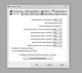
Also, click the "hammer" symbol on the top line and set the following options to automatically delete files (.raw and other files) everytime you close the program.
If you have run a simulation already then search your PC for .raw files and delete them. They can grow to be huge.
As you have the program installed here is a simple PSU (a voltage doubler) that will get you a started on running and probing circuits. Just unzip the file and put it in docs and either click the file (if a MAC will allow) or open Spice and click file and "open" and browse for it. Click the running man at the top to run it and use the cursor to probe the circuit.
Not sure how it works on a MAC, but if its like Windows then by default the files are stored in amongst the program files. I would advise you to save any simulation files you create in a normal folder like docs etc.
Also, click the "hammer" symbol on the top line and set the following options to automatically delete files (.raw and other files) everytime you close the program.
If you have run a simulation already then search your PC for .raw files and delete them. They can grow to be huge.
Attachments
Thanks a lot. The Mac version doesn't have any of the toolbars that appear in the Windows version (unless I have done something wrong). This is all you get:
I also am a bit daunted by the need to profile every component I add. For example, I can add a capacitor and fill in its capacitance but I have no idea about its series inductance etc. So it's going to be a slow learning curve. Learning how to probe LTSPICE while learning what probing is, how to do it and what to look for is a steep curve.
Thanks for the reference to the book. I read a couple of reviews and the Amazon description. It seems rather daunting for a complete newbie to electronics! I feel like I am having to explore the deep end rather than hopping in at the shallow end and wading deeper.
Can I ask a couple of super basic questions in order to try to get things into a better perspective? When one mentions transformer ringing is this a topic (somewhat) separate from a discussion of filtering AC noise from a DC voltage or is this much the same thing? Is a snubber on the transformer secondary and a CLC filter intended to tackle the same issue? In a basic single voltage power supply such as the challenge I have set myself, is it typical or good to see a CLC filter or would one deal with any transformer ringing at the secondary and then simply run a cap/reg/cap setup such as the one I already have?
I built the "dim bulb tester" this afternoon. I followed the direction given here. At the moment I have a 100W bulb fitted. Thanks again for the safety advice.
An externally hosted image should be here but it was not working when we last tested it.
I also am a bit daunted by the need to profile every component I add. For example, I can add a capacitor and fill in its capacitance but I have no idea about its series inductance etc. So it's going to be a slow learning curve. Learning how to probe LTSPICE while learning what probing is, how to do it and what to look for is a steep curve.
Thanks for the reference to the book. I read a couple of reviews and the Amazon description. It seems rather daunting for a complete newbie to electronics! I feel like I am having to explore the deep end rather than hopping in at the shallow end and wading deeper.
Can I ask a couple of super basic questions in order to try to get things into a better perspective? When one mentions transformer ringing is this a topic (somewhat) separate from a discussion of filtering AC noise from a DC voltage or is this much the same thing? Is a snubber on the transformer secondary and a CLC filter intended to tackle the same issue? In a basic single voltage power supply such as the challenge I have set myself, is it typical or good to see a CLC filter or would one deal with any transformer ringing at the secondary and then simply run a cap/reg/cap setup such as the one I already have?
I built the "dim bulb tester" this afternoon. I followed the direction given here. At the moment I have a 100W bulb fitted. Thanks again for the safety advice.
I've never even had my mits on a MAC so honestly haven't a clue where you go from here.
For me, Bobs book was a revelation in getting started with simulation because it detailed literally every click needed. No prior knowledge was assumed. When I ordered the book I hoped there wouldn't be to much on simulation... when I started reading it I wished there was more.
Generally we don't add extra info to the standard components such self inductance etc A snubber across the secondary supresses noise and ringing, ringing that can be caused by the diodes in the bridge dropping out of conduction each half cycle.
I think the first step has to be to see if you can get all the LTspice options showing on a MAC.
I bought the book. Even the introductory stuff is way above my knowledge level but I will wade my way through as much as I can! It is interesting to learn.
I have some "best practice" and safety questions regarding installing this transformer. As I am in the UK I need to wire the primaries in series, using the blue and brown and jumpering grey to violet.
When I purchased the transformer I had thought that 2 secondaries of 15V meant that I could use one and tuck the other away for later use. I now see from footnote 1 on the datasheet that this is not the case. In any event, I only need 1 x 12V output for now. So I need to wire the secondaries in parallel - use black and yellow, and jumper black to orange and red to yellow.
For each of the primary (blue and brown) and secondary (black and yellow), which one should be connected to Live and which to Neutral?
What's good practice for the dealing with the wires that need to be jumpered? I presume one cuts them short, solders them and insulates with heatshrink sleeving but want to check. Lastly, if the long primary leads aren't quite long enough to reach the IEC inlet, again, what's best practice? I assume it is best to run a length of good quality, shielded power cable through the enclosure and again cut the existing primary leads short, solder and shield with heatshrink?
Sorry for the basic questions but given this is the first time I am doing this and AC is involved I want to make sure I am doing everything safely.
The book will be a great help and Bob has all the examples mentioned in the simulation section on his site ready to download and run in LTspsice.
With the transformer I would still recommend using the bulb tester initially while determining and connecting the windings. The data sheet looks 100% correct but you never know. If you got the phase of a winding wrong the current draw would be immense and the bulb saves all that.
As you have typed... connecting secondaries to L or N NO. The secondary's must NEVER contact the primary.
It looks like you need to connect black to orange and red to yellow to place one winding in parallel with the other.
With the transformer I would still recommend using the bulb tester initially while determining and connecting the windings. The data sheet looks 100% correct but you never know. If you got the phase of a winding wrong the current draw would be immense and the bulb saves all that.
As you have typed... connecting secondaries to L or N
NO. The secondary's must NEVER contact the primary. It looks like you need to connect black to orange and red to yellow to place one winding in parallel with the other.
Hi - not what I meant.
I meant for the in-series primary there will be blue and brown to connect to the incoming AC. One of these needs to be connected to the Live of the IEC inlet and one to Neutral on the IEC inlet. Does it matter which way around?
For the parallel-wired secondary (black and orange paired and red and yellow paired) one of these needs to be connected to the diodes at point L on my hand-drawn diagram me (A on the schematic I drew of the full-wave bridge rectifier) and the other at point N. Again, does it matter which one goes to to each?
The descriptions here don't say which way around these 2 pairs are connected.
I will absolutely be using the bulb tester. Don't worry. I'm very glad to have that thing to hopefully reduce risks here!
On the book, yes, I have now skipped to the section on simulation.
Ah.. OK
I would stick to convention and wire brown to live and blue to neutral simply to keep to standard colour schemes but it doesn't matter operationally for a transformer. The same applies to the correctly paralleled secondary. You can wire it either way round to the bridge. There is no difference.
I would stick to convention and wire brown to live and blue to neutral simply to keep to standard colour schemes but it doesn't matter operationally for a transformer. The same applies to the correctly paralleled secondary. You can wire it either way round to the bridge. There is no difference.
Thanks Mooly
Funk1980, have you tried using the Mac version that was released in August?
I'm making some progress with LTSPICE for Mac but it is a little like poking around in the dark - both because of my limited knowledge of electronics and limited knowledge of SPICE. The Mac version doesn't have the toolbars but it seems to all be there. It seems that the equivalent of "Edit Simulation Command" in Windows is just a text editor requiring one to know how the commands/fields end up in the text string.
I've linked to the (very basic) asc file I have so far. I can't figure out a few things, namely:
- the circuit presumably needs some sort of load or Vout representation after C3 (EDIT: I think I have fixed this?)
- I just picked a generic Schottky diode for the bridge diodes. I can't see how to refine this for the Cree diodes I have.
- same thing for the regulator. I don't have the information to model the Fidelity Audio SPower HC regulator (+12V, circa 5V drop)
- I'm not getting the AC voltage I was expecting to measure (15V) nor the level of DC after rectification (I was expecting circa 15 x 1.4 - 2 = 19V)
etc etc
Until I get these basics right it's hard to move forward. I will keep at it.
Last edited:
- Status
- This old topic is closed. If you want to reopen this topic, contact a moderator using the "Report Post" button.
- Home
- Amplifiers
- Power Supplies
- Help a novice steadily build a linear 12V power supply?