...also the Panasonic was the proper value, 3300pF, not 33pF.
Thanks 6, I wasn't looking at a schematic, because it wasn't posted.
Hey, I learned something from all that time you put in to helping me.


You can omit, but Shocked The Simpsons GIF - Find & Share on GIPHY
Last edited:
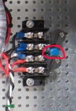
Apologies if this has been asked many times before but for 120V operation are there three thermistors used (two at transformer primaries and one for PSU ground)? I'm not sure from the offset placement of the ground thermistor on the schematic if it's only for 240V operation.
I'm trying to track down some hum in my Aleph J (inaudible on inefficient speakers but there on my Volti K-horns). I'll also be moving the output grounds from the amp boards to the PSU star ground and maybe the same for the signal grounds. Thanks!
I'm trying to track down some hum in my Aleph J (inaudible on inefficient speakers but there on my Volti K-horns). I'll also be moving the output grounds from the amp boards to the PSU star ground and maybe the same for the signal grounds. Thanks!
6, or one of you guys, the 3.3nF X1-Y2 rated to go in parallel with the trans primary, I have a couple 10nF sitting here, cool to use those in place of the 3.3nf?
JT
Should be all fine.
Actually in the higher end iec connectors of Schurter, they use 68nf capacitance.
4304.4095 Schurter | Mouser United Kingdom
See the data sheet, page 3 for CX capacitors values.
Obviously I am assuming that 10 nf ones you have handy are line voltage X rated, very important to double check.
Thanks for the input, that cap is to keep trash from making it's way back to the AC mains right? If so, how do I know what vales is best, besides trusting NP values? Teach a man to fish thing here......
Thanks for the input, that cap is to keep trash from making it's way back to the AC mains right? If so, how do I know what vales is best, besides trusting NP values? Teach a man to fish thing here......
Main reason for that capacitor is actually to avoid electrical sparks in the switch contact points when you turn on/off the switch.
Btw, trusting NP’s values is always a very good idea. Well, he is the mastermind behind the design.
Is this what you are looking for?But a very compact rectifier board which allows for custom snubbering + choice of diodes would be very nice. Perhaps one with surface mount components so that it cold be fit nicely in place of the standard bridge. I'm surprised one doesn't already exist.
I guess one day I could re-design it to use fast diodes too, but the 100x100mm pcb size makes it about the cheapest one can do unless you want to get into a CRC design, use multiple ecaps etc, but I do wonder if it is really necessary, there were many great amps designed using these simple principles.
Attachments
Last edited:
I think an aggressive and motivated person could succeed, using four of the ST "Field Effect Rectifier Diodes" in TO-220, plus Cx in SMD, plus Cs in SMD, plus Rs in SMD. This amounts to a wager: that the incredibly low Vfwd of those diodes, prevents them from overheating, even with no heatsinking whatsoever.
can i ask what happens if i split the power supply into two? in the build guide, they have the metal links for grounds between the two halves. if i split them into two , can i join all the grounds to the chassis ground and would that be noisy? + what is the difference between AUD ground and GRD on the power supply markings?
Rick,Yeah I guess so, now that you mention them, I retract my statement of not doable. Pretty cheap devices, nice. FERD30SM100ST, FERD40H100STS look to be good ones to use.
Next rev. of my rectifier design I guess, save on the expense of a heatsink.
Until you do this new design (in which I would be very interested), do you have any of the boards available which you show above?
Ron
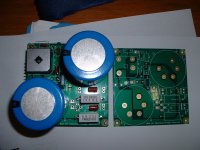
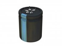
I have three of them, these where made in 2015, gold plated so good for ever. I have the BOM loaded in Mouser, I see that the ecaps are in stock
598-382LX223M080B062
The picture they show is not accurate, the ones I spec'd have 5 pins, 25mm pin space, VS type, 50mm diameter
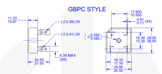
If I did that design to replace the GPC bridge rectifier, how would you want it to be mounted? one hole in the middle, to use a standoff, what's to stop it rotating around?
598-382LX223M080B062
The picture they show is not accurate, the ones I spec'd have 5 pins, 25mm pin space, VS type, 50mm diameter
If I did that design to replace the GPC bridge rectifier, how would you want it to be mounted? one hole in the middle, to use a standoff, what's to stop it rotating around?
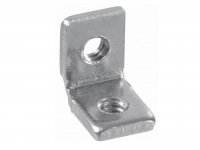
As far as a new board, the idea of a dedicated small rectifier circuit with snubbers, and designed to work with CT transformers is very attractive because it can be used as a simple, fast upgrade to the power supply of many existing amplifiers. And there is no commitment to a specific PSU design. So one could use it with the stock e-caps, or as part of an entire PSU upgrade. A drop in replacement would be really great, but I would be pretty happy with anything that was just small--there's not a lot of room in some of these amps if you're not building from scratch. Vertical mounting using a single screw (the same one used for the stock bridge) with something like the L-bracket below is one idea. Or flat, screwed in relatively tight with a rubber washer could keep it from turning. I would think something like this would be interesting to a lot of people.I have three of them, these where made in 2015, gold plated so good for ever. I have the BOM loaded in Mouser, I see that the ecaps are in stock
598-382LX223M080B062
The picture they show is not accurate, the ones I spec'd have 5 pins, 25mm pin space, VS type, 50mm diameter
If I did that design to replace the GPC bridge rectifier, how would you want it to be mounted? one hole in the middle, to use a standoff, what's to stop it rotating around?
Regarding your current board, below is what they show me for the e-cap you reference--it looks like what you describe. If I want to use quiet diodes I could use a mini-board with appropriately placed stand-off's. Otherwise the specs of these parts as is would work fine for several amps I have (e.g. the DH-200/220). And the board is designed to work with a CT transformer, and gives me snubbers and bleed resistors.
What are the dimensions of the board?Ron
Attachments
- Home
- Amplifiers
- Power Supplies
- diyAudio Power Supply Circuit Board v3 illustrated build guide