ESP is a fantastic resource so I don't like complaining about the quality of a tiny portion of it. But sometimes I think he makes it up. (maybe we all fall into that trap occasionally?)Hi Andrew T,
Its been bugging me where i came up with the 500va thing. Just so you dont think i was making it up (whether its correct or not is a different matter)...
On esp here:
Mains DC and Transformers
"It's also worth noting that DC is usually not a problem with toroidal transformers of 300VA or less. Their primary resistance is usually high enough that any DC will have little effect. With larger transformers (500VA and above), the DC resistance is usually so low that even a very small offset will cause mechanical noise due to saturation."
However, as i have put a dc blocker on mine its most likely to be loose windings, which is annoying as it wasnt cheap. (maybe it was, around £100 for a sedlbauer).
I can't see why an extra half ohm of primary resistance can suddenly remove mechanical humming. i.e. I see no reason that a properly designed and manufacturered pair of 300VA and 500VA toroid transformers should not be mechanically as silent as each other.
I have to say, I'm not actually sure the transformer has loose windings. I'm wondering if it's the steel sheet it's bolted to and the field is interacting with it. Of course the transformer itself could be vibrating it could be acting as a sound board. I should really add some mild damping underneath it.

I find that when trying to solder to a big area plane where the pad is not fitted with thermal relief slots, that turning the temp control up from 290 C to 340 C and loading the tip with a big blob of molten solder and adding a bit of extra flux to the pad is necessary to get the plane up to temp and for the solder to flow.
Then attach the component leg.
Long term plane heating with the component leg touching will probably damage the component.
Then attach the component leg.
Long term plane heating with the component leg touching will probably damage the component.
I am building the f6 amp and using the v3 psu. my psu will use the antek a5-3218 (300va and18v secondaries) I chose the diodes on the BOM fep30dp-e3/45gi-nd these are 15amp 200v. reading thru the thread a second time it calls for 30amp diodes. will 15amp diodes work
15 amp is fine.
Correct wiring for rectifier bridge for PSU v3 board?
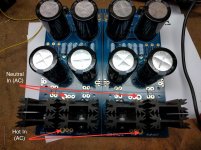
I have read and re-read this (entire) forum, but cannot definitively tell exactly how to connect the 18V AC leads from my transformer to the PSUv3 board using the diode rectifier bridge. I've posted a photo of my current build below -- and indicted what I *think* I understand about how this should be connected to the 18V AC input. I know this is a trivial question and one I should be able to figure out (or infer) but I simply don't feel confident that I'm understanding this correctly. Thank you in advance!
I have read and re-read this (entire) forum, but cannot definitively tell exactly how to connect the 18V AC leads from my transformer to the PSUv3 board using the diode rectifier bridge. I've posted a photo of my current build below -- and indicted what I *think* I understand about how this should be connected to the 18V AC input. I know this is a trivial question and one I should be able to figure out (or infer) but I simply don't feel confident that I'm understanding this correctly. Thank you in advance!
Attachments

Moved OT conversation about F5T gain and preamp choices to it's own thread -
http://www.diyaudio.com/forums/pass-labs/304826-f5t-gain-structure-preamp-choice.html
Moved OT conversation about F5T gain and preamp choices to it's own thread -
http://www.diyaudio.com/forums/pass-labs/304826-f5t-gain-structure-preamp-choice.html
You're right. Thank you.
Sent from my iPhone using Tapatalk
You have 70,000uF 50V caps that fit that PCB??
You'll need a bigger mains fuse.
Nothing else really changes in the PSU... other than your inrush current on power-up will be immense.
You may seriously want to consider using 4 of the caps. It's still much bigger than stock.
I realised this 6L6...I had a power supply board with 8 X 4700uF caps, that does not trip my MCB's, but when I use the ones with 8 X 15000uF 63V caps, my 10A MCB's trip on restart...I am going to use CL-60's as per your suggestion, but not sure how far they can help me...I am sure they will get very hot very soon and may not support me on a restart.. Any calculations how this inrush current increases with Caps sizes!!
- Home
- Amplifiers
- Power Supplies
- diyAudio Power Supply Circuit Board v3 illustrated build guide