I plan on building an F5 turbo version 2 with the rail voltages. i.e +/-32V in a non-cascode build. The Antek 6224 transformer used by 6L6 (http://www.diyaudio.com/forums/pass-labs/254056-f5turbo-illustrated-build-guide.html) is no longer available. The closest they have is the Antek 10425 which is a 1000VA with 25V output (AN-10425 - 1000VA 25V Transformer - AnTek Products Corp). Is that suitable to use or is the VA too high?
Or would it be preferable to use the Hammond 1182T24 (625VA, 48V @ 13.02A in series/24 @ 26.04A in parallel), or 1182U24 (750VA, 48V @ 15.63A in series/24V @ 31.26A in parallel)?
(Hammond Mfg. - Toroid Power Transformers - (1182 Series))
Or is there another option?
thanks
Or would it be preferable to use the Hammond 1182T24 (625VA, 48V @ 13.02A in series/24 @ 26.04A in parallel), or 1182U24 (750VA, 48V @ 15.63A in series/24V @ 31.26A in parallel)?
(Hammond Mfg. - Toroid Power Transformers - (1182 Series))
Or is there another option?
thanks
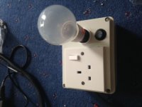
Tester built !
Hi Andrew, or Anyone else that can help ?
the tester is made with a 100w bulb. I'm still blowing fuses . I have a 3A fuse on the wall plug , 6.15A in the IEC and a 2A after 2x CL60 in series - the bulb connected to the secondaries …..
thank you ,Richard
Have you built the mains bulb tester?
Hi Andrew, or Anyone else that can help ?
the tester is made with a 100w bulb. I'm still blowing fuses . I have a 3A fuse on the wall plug , 6.15A in the IEC and a 2A after 2x CL60 in series - the bulb connected to the secondaries …..
thank you ,Richard
A 100W bulb will not blow a 3A fuse even when the output of the bulb tester is shorted.
You have built the tester incorrectly.
The bulb tester goes in the Mains circuit with a mains plug top to plug into the wall outlet and a mains socket to supply the mains powered project.
You have built the tester incorrectly.
The bulb tester goes in the Mains circuit with a mains plug top to plug into the wall outlet and a mains socket to supply the mains powered project.
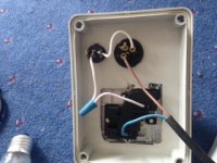
Can you confirm what I think I am seeing?
The Brn comes into the bulb holder from a plug top.
The wht comes out of the bulb holder and goes to a switch.
another wht comes out of the switch and couples (under the blue tape) to a further wht to the Live of the switched output socket.
Blue comes from the Neutral of the output socket and goes into the cable then to a plug top Neutral.
What is on the other end of that two core (Brn Blu) cable.
You don't need those two switches. It appears you have them correctly wired, so don't remove them.
You can check your wiring with a DMM set to ohms.
close both switches. Insert a bulb. Measure the resistance from Live on the input plug to Live inside the Output socket receptacle.
It should measure the same as the bulb cold resistance.
When you switch either switch with the bulb in place it should read open circuit.
When you remove the bulb it should read open circuit (with both switches closed).
I see an earthing terminal on the back of the bulb holder and this usually indicates a brass/metal bulb retention bayonet.
Is there exposed brass/metal around the bulb holder?
You need to be extra careful that a loose or broken wire cannot make the metal bayonet LIVE !!!!
If you have exposed metal, then I suggest you add a 3wire mains cable and "Earth" the bayonet metalwork.
Last edited:
Definitely wired wrong.
The mains current enters the tester plug top goes THROUGH the bulb filament to the tester socket. If any switch is open or the bulb removed, the resistance MUST measure open circuit.
The Neutral from Tester Plug to Tester Socket should ALWAYS measure <<0r1
The mains current enters the tester plug top goes THROUGH the bulb filament to the tester socket. If any switch is open or the bulb removed, the resistance MUST measure open circuit.
The Neutral from Tester Plug to Tester Socket should ALWAYS measure <<0r1
Light bulb tester thread:
http://www.diyaudio.com/forums/power-supplies/167579-light-bulb-tester.html
http://www.diyaudio.com/forums/power-supplies/167579-light-bulb-tester.html
Rich -
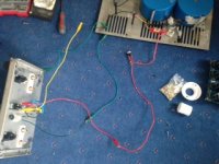
You mentioned that you have the bulb-tester on the secondaries - just to clarify, the bulb-tester should be wired in the place of a mains lead from your wall to the amp's IEC (or whatever you have for mains inlet.)
The first place to check is the wiring of the transformer secondaries to the bridges... an error there will immediately blow fuses. Specifically if you have a secondary wired with the winding phase turned 'inside-out'.
I'm flying the next 2 days, but can skype on Monday.
Remove all the white wires.
Wire Brn from Plug Top to Bulb Holder.
Wire Wht from Bulb holder to LIVE of socket.
Wire Blu from Plug Top to NEUTRAL of socket.
Only the switch in the socket and the bulb filament is in the LIVE half of the bulb tester.
There should be nothing in the Neutral from Plug top to socket.
Remeasure the resistances.
Report back.
- Home
- Amplifiers
- Power Supplies
- diyAudio Power Supply Circuit Board v3 illustrated build guide