You're right, I wasn't thinking about the effect of capacitor bank charging. (I'm not even sure what that means! I am an untrained newbie...) Capacitors are 22,000uf, 50v. I will stick with the 300VA transformer - I already have it, and being in New Zealand at the end of a very long supply chain it's quite an expensive item to replace. Maybe a bigger transformer for another build in the future.
The Soft Start Board I am thinking of is the DIYaudio store Soft Start Board - is that what C60 refers to?
Thanks for your reply - very helpful!
The Soft Start Board I am thinking of is the DIYaudio store Soft Start Board - is that what C60 refers to?
Thanks for your reply - very helpful!
Whit that capacitor bank (88,000uF) and with that nominal voltage (50V DC = low ESR), you'd be exposing the transformer windings/bridge rectifier (not to mention the mains ON/OFF switch!!!) to a short circuit. Hence, definitely use the CL60 (a single one, for 240V AC connection). This will server the soft-start purposes; will limit the start-up current (initial charging current) by introducing the CL60's cold resistance in series with the short -> presented by a fully discharged capacitor bank.
A (hopefully) final question...
Will a 15 ohm thermistor work? Or does it need to be 10 ohm?
I can get these locally:
15Ω Epoxy Dip NTC Thermistor | Jaycar Electronics New Zealand
Thanks in advance!
Will a 15 ohm thermistor work? Or does it need to be 10 ohm?
I can get these locally:
15Ω Epoxy Dip NTC Thermistor | Jaycar Electronics New Zealand
Thanks in advance!
I am using Ametherm SL15 60002 thermistors in my class A amp PSU. Since I am on 120VAC, I used 2, each one in series with one winding of a dual primary transformer. These have a cold resistance of 60 Ohms, which is high by some standards but results in a very low inrush current. They are effectively in parallel, so the inrush is only around 4 Amps.
My amp dissipates about 160 Watts at idle. These are rated at 2 Amps steady-state max. At 50% max current (around 1 Amp each), the hot resistance is rated at about 2 Ohms. I am seeing a voltage drop of about 3 VAC across them. This is a little high - but I would rather trade off low stress on the transformer, rectifiers, and caps for a little loss of regulation. Since this is a class A amp, there is not a lot of fluctuation in the load requirements. If you are building a high power A/B amp, I would use a lower value thermistor.
The Ametherms get toasty warm, but they appear to have a ceramic coating, which I would prefer over epoxy. Also, you want to mount them with long leads intact so they warm up correctly. Use high-temperature insulating sleeves over the leads.
You need to carefully consider your PSU load and look at the datasheets before choosing a particular thermistor, but these are working fine for me.
I'm using SL15 47003 in my M2X on 230VAC. Works fine for me too. A few volts drop across it too. https://www.ametherm.com/datasheetspdf/SL1547003.pdf
I have seen elsewhere in the forums where people seem to prefer the Ametherms.
BTW - one thing you might consider is getting a clamp-on ammeter for measuring AC current safely. Also useful for measuring the secondary currents out of the transformer. If you get one that is true RMS, you can also see the capacitor ripple currents after your rectifiers.
BTW - one thing you might consider is getting a clamp-on ammeter for measuring AC current safely. Also useful for measuring the secondary currents out of the transformer. If you get one that is true RMS, you can also see the capacitor ripple currents after your rectifiers.
I'm building this PSU for an F4 build. Couple of questions:
1) What is the purpose of the 6 optional .47R resistors. Can I assume of I'm not using them I should install a jumper for each?
2) What should the value of the R9 & R10 bleeder resistors be? I'm using a 500VA 115 x 20V PT.
3) I bought the hardware kit for the 4U deluxe cabinet. Does it come with the hardware to mount the diode to the heatsinks on the PSU?
Thanks!!
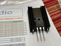
OK, one more question. I'm mounting the heatsinks and diodes. I ordered the part number on the BoM, and that's what I was sent, but they have 3 legs and the one shown in the build has 2.
1) What is the purpose of the 6 optional .47R resistors. Can I assume of I'm not using them I should install a jumper for each?
2) What should the value of the R9 & R10 bleeder resistors be? I'm using a 500VA 115 x 20V PT.
3) I bought the hardware kit for the 4U deluxe cabinet. Does it come with the hardware to mount the diode to the heatsinks on the PSU?
Thanks!!
OK, one more question. I'm mounting the heatsinks and diodes. I ordered the part number on the BoM, and that's what I was sent, but they have 3 legs and the one shown in the build has 2.
Attachments
Last edited:
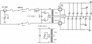
1. the power supply is CRC, where the R is used to reduce the ripple. If you install the links in parallel with the resistors, the power supply would become just a single bank of capacitors. So, NO - do not install the links.
2. They can be anything between 4.7K and up.... I used 6.8K because that's what I had close at hand. Even 10K will do....
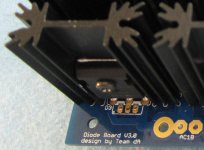
3. It does not. You need fairly short screws here... because they may hit each other when you mount everything on the PCB
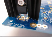
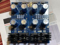
4. Use the dual diodes as specified in BOM. Ignore the photo that shows a single diode mounting option. See the photo I attached.
2. They can be anything between 4.7K and up.... I used 6.8K because that's what I had close at hand. Even 10K will do....
3. It does not. You need fairly short screws here... because they may hit each other when you mount everything on the PCB
4. Use the dual diodes as specified in BOM. Ignore the photo that shows a single diode mounting option. See the photo I attached.
Attachments
Last edited:
You are living on the edge with 25 WVDC caps, if I read your post correctly and you have a 20 VAC transformer (what is PT?).
You need to understand some basics of PSU design and safety: Assuming a full-wave bridge, a 20 VAC transformer secondary will produce (1.4 x 20 VAC) - 2 V rectifier bridge drop = 26 VDC across the caps.
But this is under load. With no load, the voltage across the caps will be higher, depending on the transformer droop.
Best case, the caps will have a short life span. Worst case, they will explode. Suggest 35 WVDC caps for your application.
That stinks. I wonder why I bought 25V??
Anyway, I can't find anything that's 35V (or 50V) and has the 10mm lead spacing. Most are 25mm diameters with 12.5mm lead spacing.
You probably just need to search for snap in leads instead of radial
I was just searching for audio, 15000uF, 35V and didn't find anything in stock.
I found these on ebay for $8 ea. Nichicon UFW Audio Grade Electrolytic Capacitor, 15000uF @ 35V, 20% Tolerance 721205488515 | eBay
Judging by the Mouser and Digi-key prices, it's not crazy out of line.
I found these on ebay for $8 ea. Nichicon UFW Audio Grade Electrolytic Capacitor, 15000uF @ 35V, 20% Tolerance 721205488515 | eBay
Judging by the Mouser and Digi-key prices, it's not crazy out of line.
Use the filters on Mouser to select snap-in, diameter, working voltage, and capacitance, etc. You'll find what you need. And forget "audio" - that has little to do with basic filtering capability. You want caps with good ripple current handling and reasonably low ESR (equivalent series resistance).
Also, Cornell Dubilier has an interesting online calculator for figuring out derating values and cap life: CDE Plug-in Life / Temperature Calculator
You'll be amazed that caps with seemingly short life ratings can last for decades if appropriately de-rated (voltage, ripple, temperature).
If you post more details of what you are trying to do and what transformer you have, etc. there is lots of help from folks here.
- Home
- Amplifiers
- Power Supplies
- diyAudio Power Supply Circuit Board v3 illustrated build guide