All things remaining equal, a physically larger / higher VA transformer could add to the consideration re: EMI and layout. This may or may not matter to you. You could have a monster chassis or separate chassis for your PSU and amp. For the M2x, more consideration might be needed over the Aleph J as an example. So, your choices can depend on a number of things, two additional variables may be your speakers' sensitivity and how hum makes you feel.
If you really notice sound differences between inrush current limiter in and out, the amplifier surely suffers from severe design flaws. Rememer that the current limiter effectively is out when the relay contacts are closed.
Best regards!
The inrush current limiter that we are talking about here consists of a single (well, for us who use 220/240V AC mains) CL60. There are no relays here in play. I mentioned the relay option as an improvement option. I do not believe you read my post, skimmed through it most likely. So, your reply does not make any sense.
I can definitely tell when the CL60 is NOT in series with the transformer primary. The sound is much better defined, especially in the bass region. It is also more spacious, in all dimensions; width and depth.
Thank you, Boky. In the first iteration of the amps, I will go the low risk route. Noob does not want get zapped ") . Thank you for outlining the other routes. I will experiment with that!
. Thank you for outlining the other routes. I will experiment with that!
Circumventing the CL60 is optional right?
Actually I got two 250 VA 18 toridy transformers on the way. The plan is to use them in 500 VA stereo configuration first and then move towards dual mono with 250 VA each. If I do not hear anything to the contrary, I am considering upping the VA to 800 VA per piece.
@ItsAllInMyHead: I settled on a Pi 4 bass reflex with 98db sensitivity. With layout, I am building a stereo chassis with an interior space of 40 cm width 30 cm depth and 30 cm height. The transformers are of the toroidy supreme audio grade with eletric and electromagentic shields. I cross my fingers that this is sufficient to fight hum.
And if there still is hum, I will consider building a separate box.
. Thank you for outlining the other routes. I will experiment with that!Circumventing the CL60 is optional right?
Actually I got two 250 VA 18 toridy transformers on the way. The plan is to use them in 500 VA stereo configuration first and then move towards dual mono with 250 VA each. If I do not hear anything to the contrary, I am considering upping the VA to 800 VA per piece.
@ItsAllInMyHead: I settled on a Pi 4 bass reflex with 98db sensitivity. With layout, I am building a stereo chassis with an interior space of 40 cm width 30 cm depth and 30 cm height. The transformers are of the toroidy supreme audio grade with eletric and electromagentic shields. I cross my fingers that this is sufficient to fight hum.
And if there still is hum, I will consider building a separate box
.
Last edited:
May I ask you, just out of curiosity, when and where you mentioned CL60 the first time? I didn't manage to find it within this thread.The inrush current limiter that we are talking about here consists of a single (well, for us who use 220/240V AC mains) CL60. There are no relays here in play. I mentioned the relay option as an improvement option. I do not believe you read my post, skimmed through it most likely. So, your reply does not make any sense.
I can definitely tell when the CL60 is NOT in series with the transformer primary. The sound is much better defined, especially in the bass region. It is also more spacious, in all dimensions; width and depth.
Anyhow, as I said before, an amplifier that enables you to listen to it's PSU is a poorly designed one, or it deliberately is an effects machine, such as a guitar amplifier.
Best regards!
FWIW, a lot of us have moved on from the CL therms, there are other options which can do the job better.
I don't have all the links, but check this one by Mark Johnson
Not Thrilled with CL-60
I don't have all the links, but check this one by Mark Johnson
Not Thrilled with CL-60
Last edited:
Out of curiosity, what would the maximum AC or DC voltage rating of this board be? I am looking for smallest insulation distance/path between AC and DC paths to determine this if any static values are unknown. Obviously clear varnish would raise it a bit, but curious if bare board insulation resistance values/dielectric strength are known.
I am looking to build a 4-5KW or larger DC single ended DC supply to be used as a lab/bench supply in order to provide power for load testing of half and full bridge inverter modules operating between 25-400KHz output. The power supply simply needs to provide DC to a current fed inverter module. The purpose of this is load testing said inverter modules post test/repair. The required DC buss volts would be up to 500VDC worst case, with a nominal working range between 100-375 VDC at 4-5KW. Obviously multiples of these boards would be required, would require substantial filtering caps and I would be using an additional large inductor as a choke on the DC link prior to the inverter/after DC supply filtering. AC XFMR primary would be variable volts to allow for variable DC. I am simply looking for lego block style construction of the PCB's as there is no need to re-invent the wheel. Also I love the community and see no reason to buy elsewhere. I do have a tech question out to Connex Elec regarding their large SMPS to see if I could do it all in a single smps/neat package.
I am looking to build a 4-5KW or larger DC single ended DC supply to be used as a lab/bench supply in order to provide power for load testing of half and full bridge inverter modules operating between 25-400KHz output. The power supply simply needs to provide DC to a current fed inverter module. The purpose of this is load testing said inverter modules post test/repair. The required DC buss volts would be up to 500VDC worst case, with a nominal working range between 100-375 VDC at 4-5KW. Obviously multiples of these boards would be required, would require substantial filtering caps and I would be using an additional large inductor as a choke on the DC link prior to the inverter/after DC supply filtering. AC XFMR primary would be variable volts to allow for variable DC. I am simply looking for lego block style construction of the PCB's as there is no need to re-invent the wheel. Also I love the community and see no reason to buy elsewhere. I do have a tech question out to Connex Elec regarding their large SMPS to see if I could do it all in a single smps/neat package.
FWIW, a lot of us have moved on from the CL therms, there are other options which can do the job better.
Not Thrilled with CL-60
Thank you, will check it out!
Dancing diodes...
Tried to find that specific post in build-guides and elsewhere, without success. Reading scm, pcb or data-sheet didn't help either... Somewhere, 6L6 was showing how he had to swap the legs of the diodes due to some inconsistencies between bom and pub (?).
Those diodes weren't the FEP30DP-E3/45, right? (I mean, I haven't to swap them legs?)
In the build guide for the PSU, he used diodes with 2 legs vs. 3. Is this what you're looking for?
diyAudio Power Supply Circuit Board v3 illustrated build guide
Sorry for weird link - I can't get it to work. I tried to link to a specific post picture. About 10 pictures down or so in the first post.
diyAudio Power Supply Circuit Board v3 illustrated build guide
Sorry for weird link - I can't get it to work. I tried to link to a specific post picture. About 10 pictures down or so in the first post.
Last edited:
diodes with 2 legs vs. 3. Is this what you're looking for?
Thanks, aimh! No, it was a 3 legged. Leg 2 and 3 had to be swapped, one of them sleeved to avoid a short...
But nevermind, all I wanted was a confirmation that the standard FEP30DP don’t need this treatment?
Hi, guys!
So just completed my PSU board, V3. For practical purposes I plan on connecting the ground NTC to one of the ground euroblocks. Before I mount the thing and changes become more complicated to perform, I just wanna ask what you guys think of my NTC solution.
I know, 6L6 had landed on soldering as the best option. I of course have no argument with that, and agree it is the best solution. What I am asking, is if connectiong to the euroblocks is good enough or not. Resistance-wise it should make no or little difference, IMO, as the NTC’s job is to create resistance.
Furthermore, I have all colors of 16AWG wire. I will be running 32v rails. Should I opt for higher gauge between diode bridges and PSU board, or is 16 AWG good enough?
Yes, I have split the bridges. And I know it is not recommended as it makes it more difficult to get a quiet ground. But I encountered space issues, and this way I can put the diodes faaaar away from both signal wires and the FE. And Nelson does it, so it can’t be that bad =)
Cheers from Norway,
Andreas
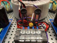
Not sure if this will help you decide or not. I am in the US, so 120VAC. Using a dual primary transformer.
One picture shows the 2 inrush limiting thermistors in series with the primary windings. I kept the leads long so that the thermistors can warm up. If you use short leads, the thermistors effectively get heat sunk to the terminal block.
There is also a safety cap across the input.
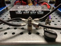
The other picture shows the isolated star ground with a thermistor connecting that to the chassis.
I split my PSU boards; one supplies +24V and the other -24V for my class A amp. They are grounded to the star ground, as are the grounds for the amp boards.
I used 16 gauge wire for the bridges, supply rails, and grounds.
One picture shows the 2 inrush limiting thermistors in series with the primary windings. I kept the leads long so that the thermistors can warm up. If you use short leads, the thermistors effectively get heat sunk to the terminal block.
There is also a safety cap across the input.
The other picture shows the isolated star ground with a thermistor connecting that to the chassis.
I split my PSU boards; one supplies +24V and the other -24V for my class A amp. They are grounded to the star ground, as are the grounds for the amp boards.
I used 16 gauge wire for the bridges, supply rails, and grounds.
Attachments
Last edited:
I am a newbie building my first DIY project a F5 power amp. I am using PSU V3 boards and have used standard BOM for purchase of parts. I am using 15,000 UF 25V Caps. My question is the BOM calls for R11 and R12, Output Snubber Resistors 1R 3W, to be used. But when looking at pictures of builds on the forum I don't see these two resistors being used. Question should I use these two resistors for R11 and R12 in my build? Thanks for your help. Lewis
Hello
I'm building a power supply for an Aleph J build, using an Antek 300VA transformer. I'm hoping to get away without a soft start (space issues), and I figure I'm right on the boundary of needing / not needing one. Thoughts?
I'm using monolithic bridge rectifiers instead on the discrete diode section of the PCBs. Should I use thermal grease when bolting them to the chassis (I have some Wakefield 120 from a previous project)?
Any advice appreciated!
The use of soft-start circuit (I think you are referring to C60 ??) is mostly determined by the capacitor bank. The more uF's and the higher the nominal voltage of the caps chosen, the higher the chance you'll need C60 (that's a lot oh "the's!!").
I would personally use the thermal grease, or even better, thermally conductive pads (similar to those used to thermally couple the CPU to a heatsink on computer motherboards).
Also, you are probably NOT thinking about the effect of capacitor bank charging currents on that 300VA transformer windings. With this in mind, I would definitely use the C60(s). This will be more gentle on those windings, that may become loose and noisy, if you opt not to use the C60(s).
However, if you choose a fully potted transformer, and you step up the game a bit, and go to 400VA, I would try to omit the C60(s). The sound improvement would definitely be noticeable. Then, make your own mind re: sound benefits vs. charging currents.
Last edited:
- Home
- Amplifiers
- Power Supplies
- diyAudio Power Supply Circuit Board v3 illustrated build guide