


Hey guys, there are some notes specs referred on the excel bom, but I do not see the actual notes? I'm talking about notes 1-4.
http://www.diyaudio.com/forums/images/diy/store/board-documentation/P-PSU-1V30/P-PSU-1V30-bom.xls
http://www.diyaudio.com/forums/images/diy/store/board-documentation/P-PSU-1V30/P-PSU-1V30-bom.xls
@thompsontechs -
Rows 65-68? Is this what you're looking for?
I guess, but I don't see them on my version of xl, there is nothing there.
I did a compatibility for older version on it and I now can see the notes. Thanks for the info that got me to figure it out.
Last edited:
I guess, but I don't see them on my version of xl, there is nothing there.
Odd. Anyway - cut and pasted from the file you linked.
Note 1 Capacitor Voltage Rating depends on your Transformer's Secondary Voltage rating!!!
Note 2 Diode Reverse Voltage rating depends on your Transformer's Secondary Voltage rating!!!
Note 3 Optimal values differ from one application to another. See forums for more information
Note 4 See this article from Hagerman Technology for information in computing optimal vaues
This is the URL for note 4 - http://www.hagtech.com/pdf/snubber.pdf
I'm not sure if this is the right place to ask. If not, I'm happy to start a new thread or find a more appropriate existing thread.
I am thrilled with the 4 Universal Power Supplies I've built. I built them all identically using the discreet / attached rectification. I'm a habitual tweaker and always want to learn more. I've come to understand that the PSU can be vital to the measured performance and the listening experience (“black background” is often mentioned) of an amplifier. I built mine with the only goal that they should work and not blow up. I placed my trust in others to provide a great circuit design and recommended BoM.
I've since read a few threads, found the power supply simulation software (a bit over my head for the moment), and read Nelson Pass's ideas on certain power supply designs.
A few questions:
Where could I find a set of recommended measurements and how to conduct them to see how a power supply performs? Related to that, how could I learn how to measure if I have "junk" in my mains and how much? I think I have a pretty clean, stable mains supply, but it'd be fun to learn more about how to measure it.
It seems that adding inductance could be a potential way to improve power supply performance. Even it it's not strictly necessary, where could I learn whether adding inductance (and how to do it) would benefit my power supplies? I do not want to build new supplies. I've invested a decent amount of money in the ones I have, and I like them. However, if there is something to learn, and I can modify the existing supplies with relatively little effort, I'd like to learn and see if I can try it and measure any performance difference.
Thanks in advance for any advice or a nudge in the right direction.

Patrick
I am thrilled with the 4 Universal Power Supplies I've built. I built them all identically using the discreet / attached rectification. I'm a habitual tweaker and always want to learn more. I've come to understand that the PSU can be vital to the measured performance and the listening experience (“black background” is often mentioned) of an amplifier. I built mine with the only goal that they should work and not blow up.
I placed my trust in others to provide a great circuit design and recommended BoM.I've since read a few threads, found the power supply simulation software (a bit over my head for the moment), and read Nelson Pass's ideas on certain power supply designs.
A few questions:
Where could I find a set of recommended measurements and how to conduct them to see how a power supply performs? Related to that, how could I learn how to measure if I have "junk" in my mains and how much? I think I have a pretty clean, stable mains supply, but it'd be fun to learn more about how to measure it.
It seems that adding inductance could be a potential way to improve power supply performance. Even it it's not strictly necessary, where could I learn whether adding inductance (and how to do it) would benefit my power supplies? I do not want to build new supplies. I've invested a decent amount of money in the ones I have, and I like them. However, if there is something to learn, and I can modify the existing supplies with relatively little effort, I'd like to learn and see if I can try it and measure any performance difference.
Thanks in advance for any advice or a nudge in the right direction.
Patrick
Last edited:
@It's Funny you should bring that up as I was just doing research on the same thing. I don't know how good the first link is, but it has good info IF it's correct lol. Hard to know for a noob. The second is from Papa himself, hope you find something useful in them: My take so far is fast and soft.
audio - Bridge rectifier: 4 diodes vs. single chip? - Electrical Engineering Stack Exchange
Power According to Pass | Stereophile.com
audio - Bridge rectifier: 4 diodes vs. single chip? - Electrical Engineering Stack Exchange
Power According to Pass | Stereophile.com
@thomspsontechs -
Thanks! The Stereophile article is the one that actually got me down this road a bit
Also this one - https://www.passlabs.com/press/power-supplies-commentary-consumers
Thanks for the link to EESE. I often find some really good content there. Some of it I can digest, some makes a sonic boom as it flies over my head so quickly.
Edited to add - If it's the right thread to do so, I'll post more of what I find if there's a common interest. Otherwise I'll PM or start another thread. PSUs for noobs?
.........
I've since read a few threads, found the power supply simulation software (a bit over my head for the moment), and read Nelson Pass's ideas on certain power supply designs. ............
It seems that adding inductance could be a potential way to improve power supply performance. Even it it's not strictly necessary, where could I learn whether adding inductance (and how to do it) would benefit my power supplies? .............
Power supply simulation is a great way to evaluate different power supply setups. I don't know which software you have tried but http://www.duncanamps.com/psud2/ is the one that I use. You can easily add/delete/change configurations and then check the resultant ripple at the supply output. By trying different types (CRC, CRCRC, CLC, etc) and varying values you can get an idea of what affects ripple the most.
A conventional bridge rectifier block (likes of KBPC2510...) vs. fast switching/soft recovery diodes... there's no rule... try both and let your ears decide. In general, with nice filtering that addresses high frequencies as well (>100kHz), the simple rectifier block sounds great.
Fast switching soft recovery diodes (switching at 100/120Hz in our case, which is nothing...), will have different sound; not better, not worse, but different. The dual diodes in a single package ones, give you two diodes in parallel, instead of one; a lot of current can go through those on a power-up, so another thing to consider... together with the ripple abilities of the smoothing caps used. Also, the wiring, in this case, is quite short... no inductance to the rescue to dampen anything...
It all goes together... the filtering, the snubbing, the length/type of wiring used, terminations to each PCB.
Build a power supply with fast switching/soft recovery diodes (short wiring!), and then play with snubbers - the type (polyester, polystyrene, electrolytes, polypropylene, brands) of capacitors used can fine-tune the sound to suit the rest of your system and your preferences.
Then, just try the rectifier blocks, and see the difference for yourself... this is a highly subjective thing.
Thanks very much for the ideas Ben and Extreme_Boky. First I'll start with trying out the simulation. Yes, Dennis, that was the simulator I found. It seems well regarded. My first endeavor will be to model my existing supply. I'll give it a go.
Regarding trying other diodes etc. At this particular point, I'd prefer not to swap out diodes. My goal is currently to see if adding inductance may not help my current supply. De-soldering heatsinks and replacing diodes or building a different type of supplies can come later.
Regarding trying other diodes etc. At this particular point, I'd prefer not to swap out diodes. My goal is currently to see if adding inductance may not help my current supply. De-soldering heatsinks and replacing diodes or building a different type of supplies can come later.
Its been a while since i posted anything in the forums - life just seems to get in the way. Anyway I have dusted off the projects I planned to start last year and am going back over the forums trying to re-edumacate myself. Believe me I have a long way to go. I am currently working on the F-5 and the power supply in particular. I am using the Amtek 4218 and plan on using the onboard rectifier circuits vs bridge rectifiers mounted to the chassis. And I am stuck on what components to use for the snubbers (input and output).
My understanding is that with the Antek 4218 the Cx is 3.3nF, Cs is 470nF and Rs is 16.9 ohms.
The parts I am considering for the input snubbers are (Mouser):
594-H332K39X7RL63J5R Ceramic Disc Capacitors .2LS 3300PF 500V 10%
81-RDEC71E476MWK1H3B Multilayer Ceramic Capacitor 47uF (but only rated to 25V - concerns me)
279-H416R9BZA Metal Film Resistors - Through Hole H4 16R9 0.1%
Do these look OK? These are not like the easiest components to find - unless its just do to my lack of experience.
For the output snubber, I understand that these may not be necessary would 605-RWHSE07TQ001R0FS Wirewound Resistors - Through Hole 1Ohms 3W 1% WW Axial be an appropriate choice coupled with a.1uF capacitor like 80-R82DC3100AA50J Film Capacitors Film Capacitors 63V 0.1uF 5% LS=5mm AEC-Q200?
Thanks for all your help - reading these forums and gleaning the amount of knowledge that is concentrated in one place is truely a humbling experience. Best regards.
Input and output snubbers - do you mean snubbers between the rectifiers and the first capacitors and snubbers after the final capacitors? If yes, then most diyAudio First Watt amplifier builders do not put them in their supplies. Note that the typical First Watt power supply does not include those snubbers.
As for the Quasimodo derived snubber between the transformer secondary and rectifiers, many builders, me included, do put those in. The values that you noted agree with the values shown here Quasimodo results (ONLY) in post #17. Mark Johnson recommends Epcos B32529 series metallized film capacitors and 0.5W metal film resistors.
B32529C0474J289 EPCOS / TDK | Mouser Canada
B32529C0332K189 EPCOS / TDK | Mouser Canada
For AC input safety capacitor:
ECQ-U2A332KL Panasonic | Mouser Canada
Attachments
Last edited:
Ben,Input and output snubbers - do you mean snubbers between the rectifiers and the first capacitors and snubbers after the final capacitors? If yes, then most diyAudio First Watt amplifier builders do not put them in their supplies. Note that the typical First Watt power supply does not include those snubbers.
As for the Quasimodo derived snubber between the transformer secondary and rectifiers, many builders, me included, do put those in. The values that you noted agree with the values shown here Quasimodo results (ONLY) in post #17. Mark Johnson recommends Epcos B32529 series metallized film capacitors and 0.5W metal film resistors.
B32529C0474J289 EPCOS / TDK | Mouser Canada
B32529C0332K189 EPCOS / TDK | Mouser Canada
For AC input safety capacitor:
ECQ-U2A332KL Panasonic | Mouser Canada
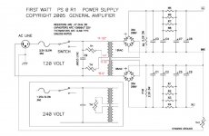
Much thanks for your help on the snubber values and part numbers. I had literally stayed up all night reading and researching that information. There are lots of threads and I have only scratched the surface. That schematic is very helpful as well especially as I was trying to understand the placement of the cl60s as well.
Kudos!
LOL - Just going back through my notes and at some point in the middle of the night I had found and printed that schematic - thinking "that would be really helpful". Oh well sometimes you have to walk away and clear your head. Thanks again!Input and output snubbers - do you mean snubbers between the rectifiers and the first capacitors and snubbers after the final capacitors? If yes, then most diyAudio First Watt amplifier builders do not put them in their supplies. Note that the typical First Watt power supply does not include those snubbers.
As for the Quasimodo derived snubber between the transformer secondary and rectifiers, many builders, me included, do put those in. The values that you noted agree with the values shown here Quasimodo results (ONLY) in post #17. Mark Johnson recommends Epcos B32529 series metallized film capacitors and 0.5W metal film resistors.
B32529C0474J289 EPCOS / TDK | Mouser Canada
B32529C0332K189 EPCOS / TDK | Mouser Canada
For AC input safety capacitor:
ECQ-U2A332KL Panasonic | Mouser Canada
what grease is that and what is its purpose (i.e. "a little grease is helpful on the full pack devices" for the PSU - from Post #1)? thanks
The grease is a thermally conductive compound for filling any air gaps between the heatsink and the device. While they should both the dead-flat, they will still have microscopic roughness which would otherwise trap insulating air.
https://www.amazon.com/heaven2017-C...B78WPQFV2WD&psc=1&refRID=HRNRC9PJNB78WPQFV2WD
That will last you forever. Use as little as possible.
That will last you forever. Use as little as possible.
thanks Jim and Jeff.
I'm finally getting started on building after 3 international moves incl. 10 city moves, two kids and a house renovation.
It's the little things like this that I need some pointers on to get started.
Jim, I'm taking photos and will do a build guide trying to emulate one of yours as I'm going, putting in the things I found helpful along the way - like this paste/grease.
- Home
- Amplifiers
- Power Supplies
- diyAudio Power Supply Circuit Board v3 illustrated build guide