Sitting here planning my F5T v2 build, trying to figure a few things out regarding the PSU board...
In the bom there are 6 optional filterresistors. When are those needed? Anything to be gained by using them for my F5T build?
I've seen recommendations using the Panasconic ECO-S1HP183EA (18KuF 50V), but the bom states 10-15Kuf. I noticed that the 18K ones are 5mm shorter, any other reasons using the 18K ones?
For the bleeder resistors (R9 and R10: 4,7R - 22K) the boom says: "Use higher resistance values for high voltage outputs." What would be appropriate for a F5T v2, with 32V rails/ the rcommended 15-18Kuf capacitors? Could I just pick anything inbetween and be happy with that?
Any input appreciated!
//Ronny
Last edited by a moderator:
For the F5T -
'Extra' filter resistors - for the F5T, you want 6 or 7 0.47ohm 3W resistors per rail.
Don't worry about the input snubbers. Not worth the bother.
Do not use the output snubber. Not helpful for Class-A amp.
The 18,000uF caps will be perfect.
Bleeder - if you have anything from about 2.2K -5K, 3W, use them. It's not a critical value, the resistor is there only discharge the capacitors when powered off. If you need to order something, use 2.2K 3W
Questions about PSU build for F-5T v2
Hi All,
Hope everyone is doing well. This is the best build guide that I have found online. Great job 6L6! We all owe you many thanks for posting such great illustrated guides...
I have a few questions regarding the PI resistors and caps specifically related to the PSU. I am building a (non-cascode) V2 F5T Stereo version (diyAudio latest FE v2.2 & v3.0 output boards). I am following the above guide.
For the PSU, (I am using the diyAudio v3.0 boards). The transformer that I was thinking of using would be the recommended +/- 24V, 600VAC unit. I am getting ready to populate the PSU boards and ran into a few "pre-stuffing" snags.
I have purchased PSU board components according to the referenced PSU v3 BOM. It lists the PI resistors (R1 thru R8) as 0.47 ohm, 3 watt units, which I have purchased and am planning on using. What I am wondering about is the slots listed as "R_Optional". Are these to be populated for a F5T v2 (non-cascode) version? I have either not found a reference or have missed it. What are the advantages of stuffing these "optional" slots with PI resistors?
Also, I am not exactly clear on the C1 thru C8 values. I have purchased 10,000 mf. units, again, following the referenced BOM. Now I read several posts that reference that they should be 15,000 mf units. Just what is best for the standard, non-cascode V2 build?
Any help would be greatly appreciated.
diyAudio Universal Power Supply Circuit Board v3 illustrated build guide. (October 2013)
(Any photo with a link directly below will go to full-size file of the photo)
This build guide will show a typical use of the diyAudio PSU v3 circuit board. This specific build will be suitable for any of the Pass/Firstwatt amps that use a +/-25V supply. If you need a higher voltage make sure you use capacitors of a suitable voltage rating for your project. You may always have a higher voltage rating, but do not use a cap with a lower voltage rating than your rails.
Useful Links
BOM - http://www.diyaudio.com/forums/images/diy/store/board-documentation/P-PSU-1V30/P-PSU-1V30-bom.xls
Schematic - http://www.diyaudio.com/forums/imag...mentation/P-PSU-1V30/P-PSU-1V30-schematic.pdf
PSU18 - My Photo Gallery
((Do not connect 2-leg TO-220 diodes as shown. See photos in 'heatsink' section.))
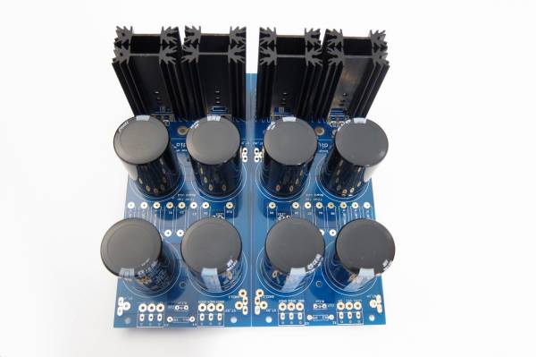
PSU36 - My Photo Gallery
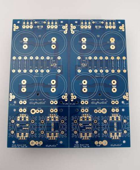
Fully stuffed
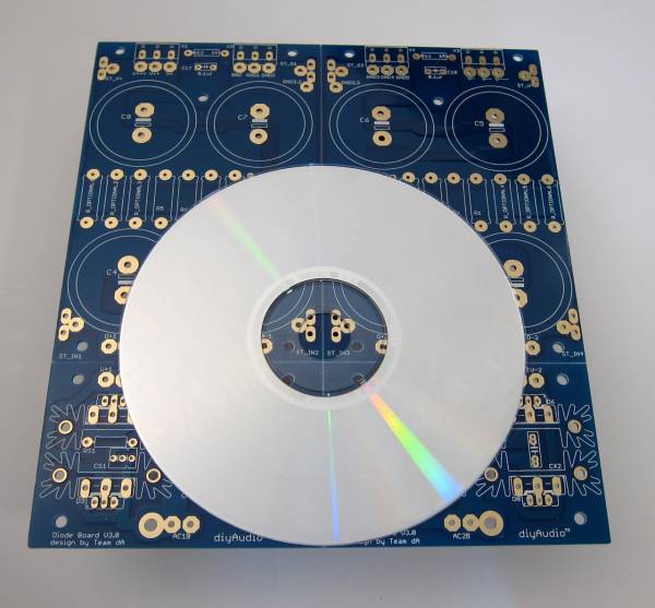
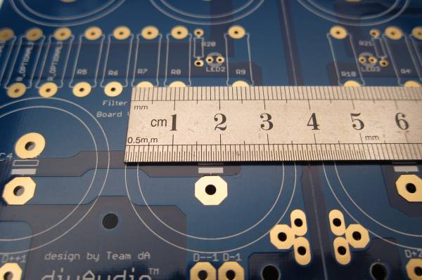
PCB scale
Dimensions -
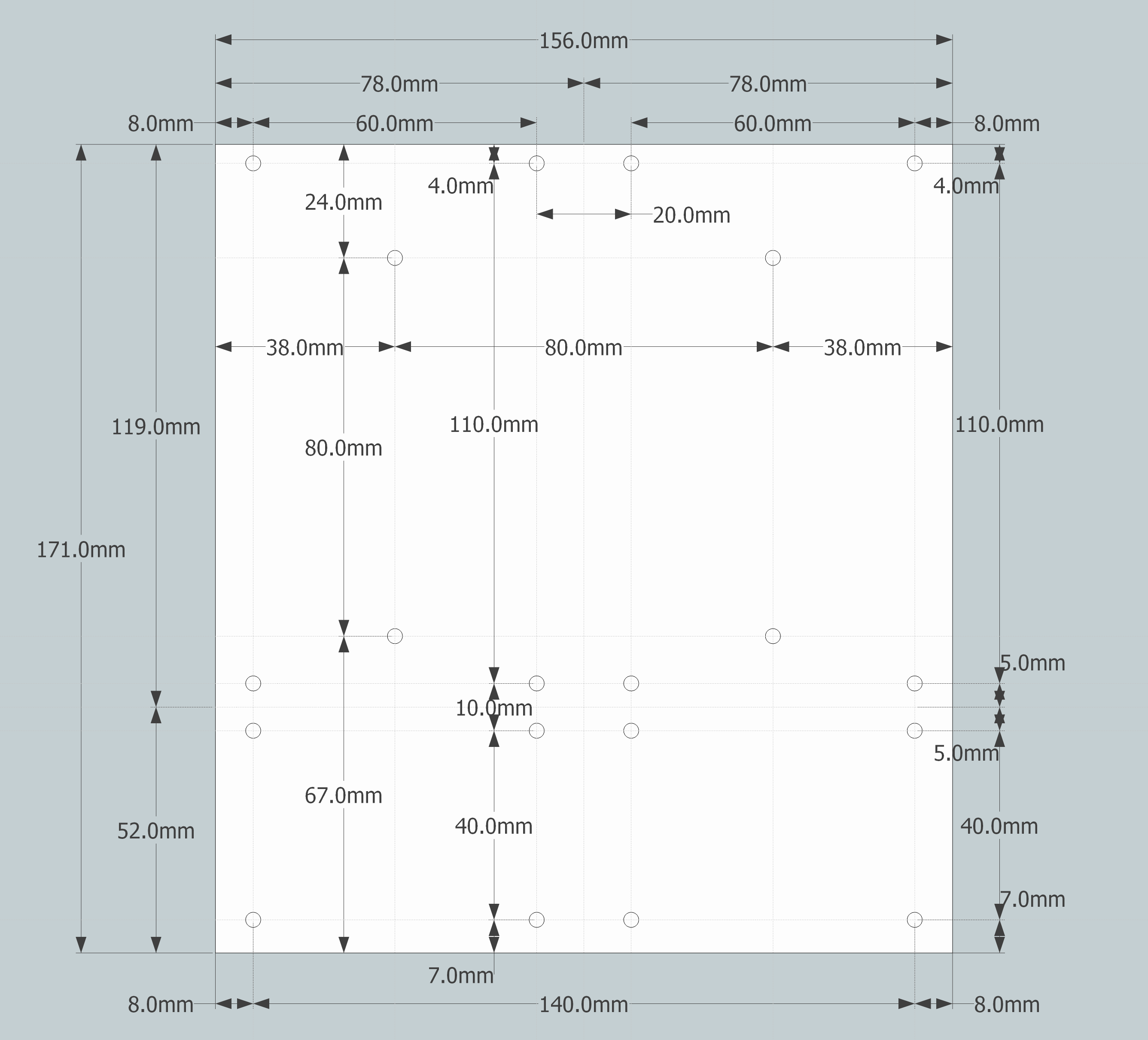
PCB dimensions

PSU14 - My Photo Gallery
The heatsinks are one inch post spacing. Look at the BOM for a specific part suggestion and find something similar that you can use. The sinks I used in this guide are of the same outer profile, so they fit the pads perfectly, but are quite a bit taller. A number of parts will be available that will work.
IMG_2134 - My Photo Gallery
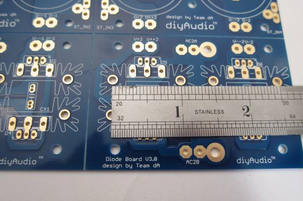
This board can accept capacitors of up to 35mm diameter.
IMG_2136 - My Photo Gallery
Equally important is the lead spacing - the caps should be 10mm 'snap in'. 10mm radial leads will work as well, but usually the bigger diameter caps have the 'snap in' leads.
For more information on dimensions of the specific parts, please consult the BOM for suggested parts, and cross-reference from that part's datasheet. http://www.diyaudio.com/forums/images/diy/store/board-documentation/P-PSU-1V30/P-PSU-1V30-bom.xls
Board features -
The bridge diode section of the board can utilize either TO-247/TO-3P (larger) package devices or TO-220 (smaller). If heat dissipation / heatsinking is not an issue, you could also use conventional axial-leaded diodes. (Not shown.)
IMG_2135 - My Photo Gallery
If you would like to use snubbers on the rectifier diodes you will find that there is room for them on the top of the PCB, and inside the heatsinks.
IMG_2141 - My Photo Gallery
If you don't find enough room there, or would like to try a different snubber layout, there is plenty of place to connect on the bottom of the PCB, as you will always have one of the d=sets of diode pads empty - you can only use one type of diode at a time, for example if you are using the TO-220, the TO-247 pads will be empty and you may make connections there.
IMG_2142 - My Photo Gallery
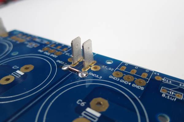
For designs that require one, there is also room for a snubber on the output. (Per rail)
Also worth noting, in this photo you can see the multiple solder pads for the output - the row towards the edge is for the euroblock connectors, and the inner row, with the larger pads, for wire. There is also a place for a blade terminal. (Near the board edge, on the outside. To be better illustrated in a later photo.)
Building / Stuffing
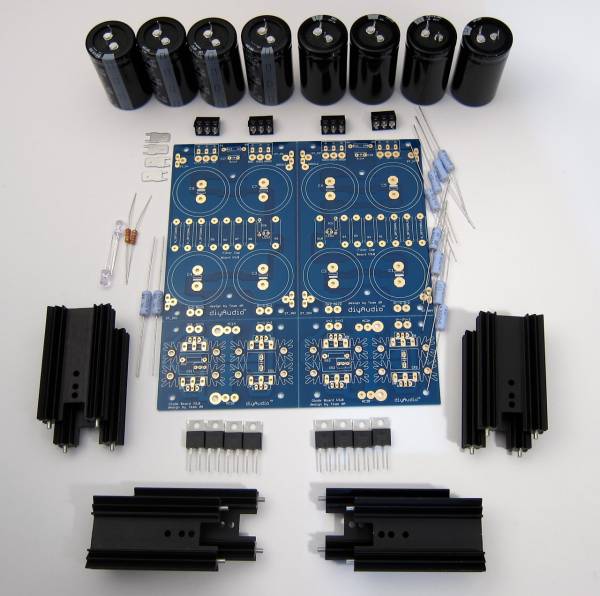
PSU41 - My Photo Gallery
This photo shows all the parts that will be used in this guide.
Starting at top and circling clockwise -
Capacitors and 'euroblock' connectors
(8) filter or 'pi' resistors
Diode heatsinks and diodes (TO-220 package shown)
(2) bleeder resistors
LED and LED resistors
AMP terminal blades
As this board has the scoring to let you separate it if you so choose, you need to notice that there is no connection from the diodes to the first capacitors nor across GND. These must be connected.
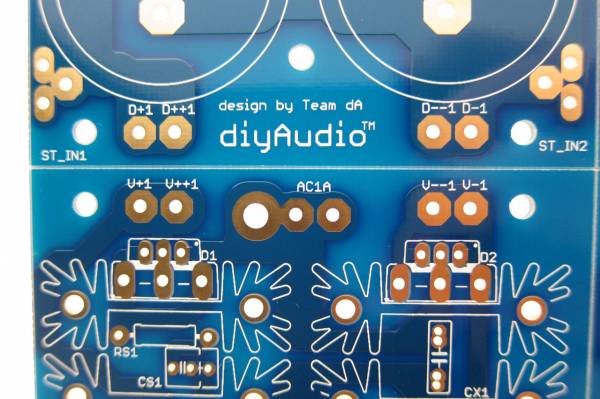
The PCB has no connection from diodes to capacitor.
The PCB also has no connection to make GND.
Since I am planning on keeping this PCB intact for the amp I am building, I need to make a connection form the diodes to the capacitor bank, and a connection to establish ground.
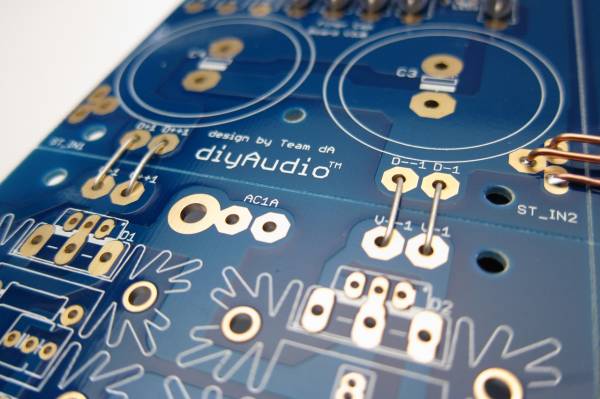
You can see all the links here (diode links not soldered in this photo)
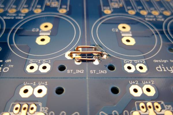
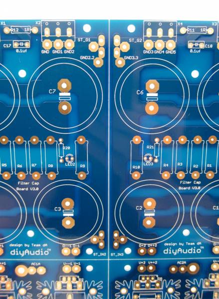
GND links. The pads on most of this PCB are all through-plated and big enough to solder from the top if you choose.
PSU28 - My Photo Gallery
In general stuffing should be from the smaller devices to the bigger devices, so the resistors and such should be first. The filter resistors are on the outside, then the LED and LED resistors (the small brown one) and inboard are the bleeder resistors.
The silkscreen markings at the LED pads are slightly obscured, and the break in the circle, indicating where the flat of the LED should go (cathode, negative, short leg) is a little bit confusing. The legs of the LED go as shown. You can also see another link at the top of the PCB where I joined GND together.
The blades are actually taller than the euroblocks, so don't solder them first!
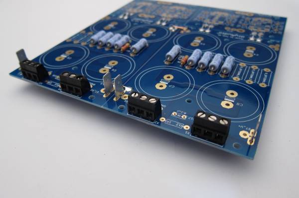
PSU27 - My Photo Gallery
The output edge shown with all the connectors in place
Capacitors -
As mentioned before, this PCB can accept caps with 10mm lead spacing and up to 35mm diameter. This photo shows 35mm caps next to 30mm. You will also commonly find some appropriate values in 25mm diameter.
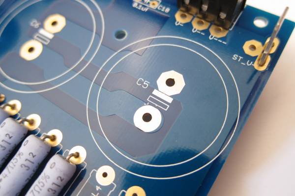
PSU32 - My Photo Gallery
The addition of the large solder pads has obscured the markings on the PCB and the ' + ' mark is somewhat hard to make out. In each case the Positive side is marked with the open rectangle and the negative the white or filled-in rectangle. Remember that electrolytic capacitors are usually only marked on the Negative side.
PSU9 - My Photo Gallery
Note capacitor direction - you can see the negative markings on each capacitor.
Heatsinks -
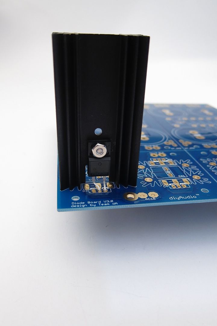
The heatsinks used in this guide were chosen as they were of proper dimension to fit the PCB, and in-stock at the time I ordered them. They are a little tall, but as Nelson Pass says, there is no such thing as too much heatsink… I do suggest you try to get something that will fit a TO-247/TO-3P package as it will also mount the TO-220, whereas the slightly narrower inner profile of this heatsink will only mount the smaller diode. Regardless, it's quite easy to get really nice, suitable diodes in whichever package - you want 30A, 200V minimum diodes.
A little grease is helpful on the full-pack devices. Secure to the heatsink with a nut and screw. This is a 4-40 screw, about the same size as M3.
Please Read - If you use a conventional TO-220 diode or TO-247/TO-3P it's a very good idea to use an insulator between the device and the heatsink. But it's not necessary - although if you choose not to the heatsinks will probably be live. The heatsinks themselves solder to the PCB and are in holes that have no electrical connection, and aluminum anodize is actually not very conductive, but I would still suggest using an insulator. (Or a full-pack TO-220)
Feel free to snap off the diode section and use monolithic bridges. They work and sound great!
NOTE - I strongly suggest not separating the capacitor board if at all possible. With it intact, you can run multiple jumpers (as shown) to tie GND together and have a low-impedance, and therefore quiet GND. Splitting it will complicate making a quiet circuit. FYI.

Example wiring.
Hi All,
Hope everyone is doing well. This is the best build guide that I have found online. Great job 6L6! We all owe you many thanks for posting such great illustrated guides...
I have a few questions regarding the PI resistors and caps specifically related to the PSU. I am building a (non-cascode) V2 F5T Stereo version (diyAudio latest FE v2.2 & v3.0 output boards). I am following the above guide.
For the PSU, (I am using the diyAudio v3.0 boards). The transformer that I was thinking of using would be the recommended +/- 24V, 600VAC unit. I am getting ready to populate the PSU boards and ran into a few "pre-stuffing" snags.
I have purchased PSU board components according to the referenced PSU v3 BOM. It lists the PI resistors (R1 thru R8) as 0.47 ohm, 3 watt units, which I have purchased and am planning on using. What I am wondering about is the slots listed as "R_Optional". Are these to be populated for a F5T v2 (non-cascode) version? I have either not found a reference or have missed it. What are the advantages of stuffing these "optional" slots with PI resistors?
Also, I am not exactly clear on the C1 thru C8 values. I have purchased 10,000 mf. units, again, following the referenced BOM. Now I read several posts that reference that they should be 15,000 mf units. Just what is best for the standard, non-cascode V2 build?
Any help would be greatly appreciated.
Use more of the same 0.47ohm 3W in the 'optional' pads. More filter resistors means less loss on a higher current PSU.
(8) 10,000uF caps is on the small side, the PSU example in the F5T article shows (16) 10,000uF caps, for 80,000uF per rail.
Something like these will work fine - ECO-S1HP183EA Panasonic | Mouser
They are 18,000uF 50V, 35mm diameter, 10mm snap-in, which is to say they fit the PCB and are as big as can be found. It will equal 72,000uF/rail, which is totally close enough.")
(8) 10,000uF caps is on the small side, the PSU example in the F5T article shows (16) 10,000uF caps, for 80,000uF per rail.
Something like these will work fine - ECO-S1HP183EA Panasonic | Mouser
They are 18,000uF 50V, 35mm diameter, 10mm snap-in, which is to say they fit the PCB and are as big as can be found. It will equal 72,000uF/rail, which is totally close enough.
F5-T diyAudio PSU Board Question
Thanks 6L6!
Thank you for the quick reply/guidance. I actually initially purchased 2 PSU boards & 16 10k caps that I can use. I will assume that I will only use 1 diode board total (for the 2 - 8 cap boards)? Or, will I need 1 diode board/rail total of (2 diode boards)?
Again, many thanks!

Thanks 6L6!
Thank you for the quick reply/guidance. I actually initially purchased 2 PSU boards & 16 10k caps that I can use. I will assume that I will only use 1 diode board total (for the 2 - 8 cap boards)? Or, will I need 1 diode board/rail total of (2 diode boards)?
Again, many thanks!
Thanks for your reply 6L6! And thanks for your clear, and easy to follow, build guide!
Haven't decided yet if going for one 800VA toroid, or maybe two 400/500VA. (There's plenty of room in the chassis, and I guess it's better to be on the upper side...) Would it make any difference going for two toroids (other than satisfying myself estetically =) )?
I'd need two PSU boards of course. And I guess 8x10000uF each would be plenty. Should I maybe even use smaller ones, say 5000uF, wich would sum up to a total of 80000uF, or does it not work that way?
Thanks again!
Ronny
If you use two transformers, remember to add in a primary/mains fuse to EACH primary.
If you use a Soft Start you can use ONE soft start circuit with ONE relay, but use a 2pole relay. One pole shorts out the resistors feeding one transformer.
The other pole shorts out the resistors feeding the other transformer.
If you use a Soft Start you can use ONE soft start circuit with ONE relay, but use a 2pole relay. One pole shorts out the resistors feeding one transformer.
The other pole shorts out the resistors feeding the other transformer.
Thanks Andrew!
I'll add an extra fuse, as you recommend. Really appreciate that you all help noobs like me, reminding us of all those little thing that we otherwise might miss!
I actually order two Soft Start boards from the diyShop, just in case. But using one circuit, as you suggest, sounds like a better solution. I tried to find a suitable relay at Mouser's, but as often got lost in all the information, and at the same time realising that I probably was missing what I was actually looking for. If you have any suggestion i'd appreciate it...
It's like trying to find the info I need here at the forum. I've spent weeks reading most of the links regarding the F5T, including all posts in the F5 Turbo building thread, just to prepare myself and get an oversight. But when it's time to get started building, and all those little questions crop up, its hopeless to find the answers I know I've seen somewhere. Being new to most of this vocabulary doesn't make things easier...
So again, I really appreciate all of you taking your time to answer all these questions, most of which you have probably answered to boredom before!
//Ronny
Last edited:
PSU v3.0 pcb MOSFET/Diode orientation question
I am getting ready to stuff the diode boards and have a question about the correct MOSFET pin orientation. This particular build guide (an excellent, easy to follow one) shows a TO-220 MOSFET with only two pins (I assume one was removed) and the reorientation (bending) of one of the pins into an adjacent pad). I am using the BOM-recommended TO-247's. It isn't quite intuitive to me why the TO-220 pins shown in this guide were reoriented.
In short, how is one to orient the pins before soldering with TO-247's? Are we to modify the TO-247's or other versions in the same matter as illustrated with the TO-220's? Is it a matter of just bolting on the diode with an insulator between the heatsink and diode and soldering in the pins in a 1-2-3 (S-D-G) as shown in the attached picture (Sorry 6L6 for butchering up one of your excellent images in this guide)? If so, why not show that with a picture or clarify with text under the images in this build guide? Maybe I am missing something (very, very possible).
Seems to me that this is a source of confusion, as I recall reading in another thread that someone was confused about this also.
Let me just say that this is in no way a complaint, as I truly appreciate all those that post on this forum and help us newbies. I just trying to understand this stuff as I go along... Without the expertise of you seasoned veterans that post of this forum, those of us that are not as knowledgeable would never get to the point of ever building our own DIY HiFi equipment. Again, thanks to all that contribute to the cause...
Any help from those more experienced would be greatly appreciated.
Attachments
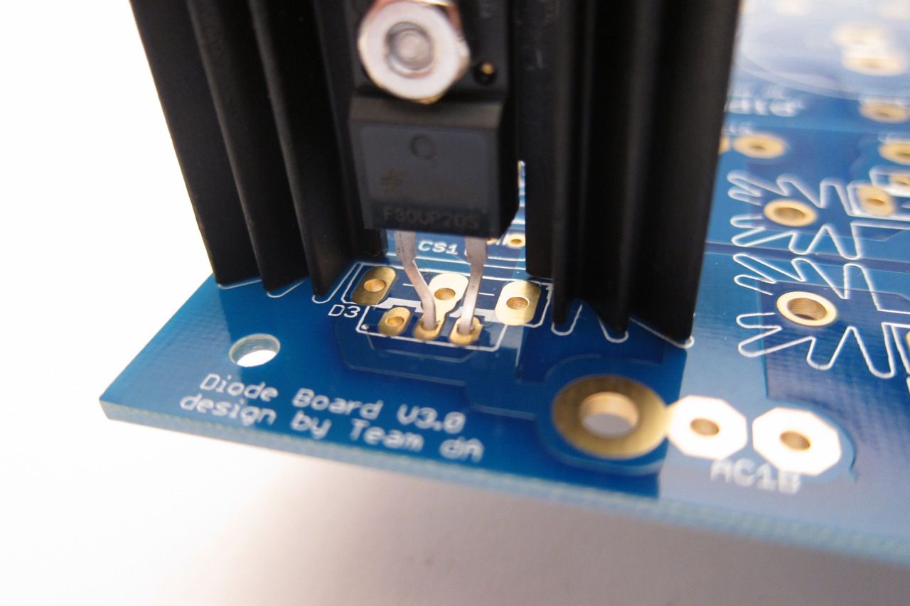
... a TO-220 MOSFET with only two pins (I assume one was removed) and the reorientation (bending) of one of the pins into an adjacent pad). ... It isn't quite intuitive to me why the TO-220 pins shown in this guide were reoriented.
No pins were harmed in the making of this guide.
The Diodes I used had 2 pins, with the Cathode on the left and the Anode on the right. The PCB is made to use a 3-pin device with the Cathode in the center, so the cathode pin needed to be bent over into the center hole.
In short, how is one to orient the pins before soldering with TO-247's?
Ummm... make sure they are straight... Not much else needed...
Are we to modify the TO-247's or other versions in the same matter as illustrated with the TO-220's?
No.
Is it a matter of just bolting on the diode with an insulator between the heatsink and diode and soldering in the pins in a 1-2-3 (S-D-G) as shown in the attached picture
Yes. And the pinout is A-K-A. (Anode Cathode Anode)
(Sorry 6L6 for butchering up one of your excellent images in this guide)?
No worries.
Seems to me that this is a source of confusion, as I recall reading in another thread that someone was confused about this also.
I think the confusion stems from my use of 2-pin diodes on a PCB made for 3-pin devices.
I used the 2-pin, IIRC, because the BOM TO-220 device was not in stock in sufficient quantity at the time, or because they were an awful lot more expensive... I needed something like 200 of them... (Group buy)
Anyway, if you have the BOM device, you don't need to do anything other than install it.
6L6,
As always, thank you for the quick reply and explanation.
I now can go forward and stuff the boards without the guesswork that was hovering regarding the pin orientation (hopefully without a cloud of smoke on initial startup!). It all makes sense now following your excellent point-by-point explanation(s)...
Once again, many thanks for the excellent work you do for all of us who follow this forum...
Snubber values ?
Hi Folks,
I'm re-building my Aleph 30 ,starting with the power supply . I'm using dual mono ,my secondaries are 24 0 24 vac , my caps are :
http://uk.farnell.com/jsp/search/productdetail.jsp?sku=776920
How do I calculate my input snubber value ?
Please and thank you ,Richard
Hi Folks,
I'm re-building my Aleph 30 ,starting with the power supply . I'm using dual mono ,my secondaries are 24 0 24 vac , my caps are :
http://uk.farnell.com/jsp/search/productdetail.jsp?sku=776920
How do I calculate my input snubber value ?
Please and thank you ,Richard
Transformer ?'s
I have finished the PSU . Transformers are 24-0-24 300va x2 ,Caps are 18000 uf 50v . Diodes are TOC 220.
My questions are on the connection of the transformers and the relation to the markings on the board .
Red = 24v + Blue = 24v - and Green and Brown become 0 .
Thank you , Richard
I have finished the PSU . Transformers are 24-0-24 300va x2 ,Caps are 18000 uf 50v . Diodes are TOC 220.
My questions are on the connection of the transformers and the relation to the markings on the board .
Red = 24v + Blue = 24v - and Green and Brown become 0 .
Thank you , Richard
Attachments
- Home
- Amplifiers
- Power Supplies
- diyAudio Power Supply Circuit Board v3 illustrated build guide