Hi,
I am doing a dual mono power supply with 500va 30vac transformer which I expect to run about 39v rails. I am using the universal power supply. I wanted to ask a few questions in selecting parts. The amp will be running about 1.5 amps line current per power supply (1 channel) cold and about 1.1 when up to temp. I have the capacitors pretty much narrowed down to these.
I have used the standard FEP30DP-E3/45 in the past which worked out great for my little F6. Will these work well at 40v? I noticed 200v reverse voltage spec which seems significantly higher than what I am doing but wanted to be sure as these boards were initially spec'ed out for Firstwatt type amps.
I also found Mark's Snubber article on here. I will read through that tonight. I really appreciate his involvement in this community. Not only his expertise but the significant amount of time that he seems to enjoy spending helping others.
Thanks 6L6. I will go ahead and start ordering some parts ") . I saw your post a while back about enjoying the sound of these diodes.
. I saw your post a while back about enjoying the sound of these diodes.
I have read that the snubbers are benificial on class A/B amps. I will be running my amp deep into class A. Do you think it is worth ordering the Quasimoto test PCB, testing and figuring out the parts that I need for the snubber circuit to prevent ringing?
. I saw your post a while back about enjoying the sound of these diodes. I have read that the snubbers are benificial on class A/B amps. I will be running my amp deep into class A. Do you think it is worth ordering the Quasimoto test PCB, testing and figuring out the parts that I need for the snubber circuit to prevent ringing?
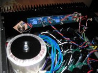
Is there any issue with stacking two transformers, one on top of the other, for a dual mono setup? Would it be a good idea to make some space between them? They will not be worked too hard so should be warm to the touch.
In all of the other dual mono amps, I see them side by side but unfortunatnly I won't have the space for that. It will be in a class A amplifier.
In all of the other dual mono amps, I see them side by side but unfortunatnly I won't have the space for that. It will be in a class A amplifier.
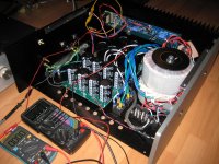

For the bolt, I went to the local hardware store and bought a short length of threaded rod that fit the bolt nut and then cut it to length. Nothing special about the rod.
I used all of the provided transformer rubber and steel plates on both transformers to help keep them centred.
That amplifier was a SissySIT, which is now a Redneck DEFISIT.
I used all of the provided transformer rubber and steel plates on both transformers to help keep them centred.
That amplifier was a SissySIT, which is now a Redneck DEFISIT.
If it is good enough for firstwatt it is good enough for me. I really like how simply Mr. Pass's amps are put together. Single piece extrusion for the heatsink and mounting plate for the boards, LEDs hit the holes on the faceplate perfectly, a few zip ties for the few wires that are in there and done. If you took the heatsink off and lay it flat, you would have access to both sides of the board for servicing (which they will likely never need) Even replace the outputs without taking the board off and no fumbling. Pretty cool.
The long shrinkwrap on the wires is a nice touch as is the AC in boards. Is the power supply a CRC network?
The long shrinkwrap on the wires is a nice touch as is the AC in boards. Is the power supply a CRC network?
DIY Universal PSU circuit question.
Why the inrush current limiter (CL-60) between the PSU board ground and the chassis ground?
I can understand a bit of resistance between the PSU and Chassis ground to prevent a loop, but aren't the 10k bleeder resisters pretty much killing any surprise current on switch on/off?
Why the inrush current limiter (CL-60) between the PSU board ground and the chassis ground?
I can understand a bit of resistance between the PSU and Chassis ground to prevent a loop, but aren't the 10k bleeder resisters pretty much killing any surprise current on switch on/off?
That's not the inrush limiter. That's the "signal" ground lift. The CL-60(s) on the primaries are the inrush limiters.DIY Universal PSU circuit question.
Why the inrush current limiter (CL-60) between the PSU board ground and the chassis ground?
I can understand a bit of resistance between the PSU and Chassis ground to prevent a loop,
Yep
Nope, and those are "optional".but aren't the 10k bleeder resisters pretty much killing any surprise current on switch on/off?
The boards are "universal", but I think you're likely referring to what might be considered a standard First Watt PSU schematic.
Thanks for the quick replies!
I am, of course, using them on the primary side.
By the way, I'm welcoming another M2X to the world this afternoon. As I had only enough CL-60s for the primaries, I put in a 10 ohm 3 watt between PSU ground and chassis. The M2X has been running a sine wave for half an hour and is happy. That 10ohm is sitting at 27C. Will need to finish up the case and plug in some speakers next.
Right. I suppose NTC would have been the right term to use. In various builds of the DIY PSU, I've seen and used a CL-60 here, following other's experience.That's not the inrush limiter.
I am, of course, using them on the primary side.
Why wouldn't you want them? They're there to gracefully drain the CAPs when amp turned off off and I assume, when on, are such a high parallel resistance that current prefers to go to the rails for the amp to use.Nope, and those are "optional".
Yes. I've seen the use of a CL-60 in many builds, and the excellent Aleph J Blog /guide here.you're likely referring to what might be considered a standard First Watt PSU schematic
By the way, I'm welcoming another M2X to the world this afternoon. As I had only enough CL-60s for the primaries, I put in a 10 ohm 3 watt between PSU ground and chassis. The M2X has been running a sine wave for half an hour and is happy. That 10ohm is sitting at 27C. Will need to finish up the case and plug in some speakers next.
- Home
- Amplifiers
- Power Supplies
- diyAudio Power Supply Circuit Board v3 illustrated build guide