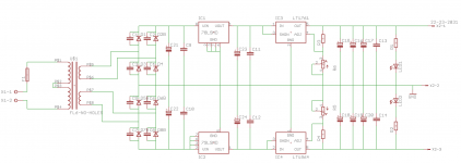
I'd like to make a simple but low noise LT1761/LT1964 PSU to provide about +/-14V @ 100mA. I'm aiming to keep the whole thing under 35mm tall and quite compact by using a PCB mounted transformer and SMD parts. Due to the input voltage limitations of the LT1761/LT1964 I've used cheap fixed +/-15V regulators before the Linear regs.
D1-D8 = SCHOTTKY, 1A, 60V, SMA package
C1-C14 = 0.1uF X7R 100V
C15-C22 = PANASONIC FC
Trafo is a Block FL6 - 6VA 2x 15V AC
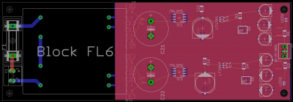
I haven't finished the layout but it looks pretty straight forward.
Any input or ways I could improve it? Are there any issues with using 2 regs like this?
D1-D8 = SCHOTTKY, 1A, 60V, SMA package
C1-C14 = 0.1uF X7R 100V
C15-C22 = PANASONIC FC
Trafo is a Block FL6 - 6VA 2x 15V AC
I haven't finished the layout but it looks pretty straight forward.
Any input or ways I could improve it? Are there any issues with using 2 regs like this?
Attachments
If you installed a CRC snubber across each secondary, instead of a capacitor across each rectifier, you'd use 2 fewer components and achieve much better EMI suppression.
If I were you, I think I might feel more comfortable running the LT final output regulators, at more than 1 volt input to output. You could put a diode in the ground leg of the upstream preregulators (giving 1.7V to the finals). Or you could swap the fixed preregs for adjustables and set them to 16V -- giving the LT final regs 2 volts input to output.
I think I might also find a handy place to install a couple of ferrite beads, perhaps in series between C23&C11 (C24&C12).
I think I might also consider abandoning the ground plane PCB layout, in favor of a star-grounding system (or a hierarchy of star-grounds, sometimes called "star on star")
Concur. Placing capacitors in parallel with rectifier diodes is not a good idea, despite the number of people who do it. That only lowers the frequency of any resonance or ringing. It does almost nothing to help actually get rid of it. A snubber is a resistor. Usually, a snubber resistor has a capacitor in series with it, so that only the unwanted frequencies have access to the resistor. A capacitor alone is mostly pointless at best, when a snubber is what is needed.
I am doing doing similar with the LT1963A/LT3015 pair. In the DDPak package in my case due to declining vision and dexterity.
Fully agree with Mark's comments.
I do not like using trim pots in fixed Vout applications - refer to the data sheet for value calculation and use fixed resistors, its much safer for the expensive thing being powered. You should be able to get very close with a parallel or series combination.
Finally the data sheets list the problems using multilayer ceramic caps as bypass on Vout - I prefer the COG dielectric or a small value stacked film surface mount.
OK. Could you give me some values to use? What power rating for the resistor?If you installed a CRC snubber across each secondary, instead of a capacitor across each rectifier, you'd use 2 fewer components and achieve much better EMI suppression.
The voltage drop for the LT regs is only 340mV. Does a higher drop make a difference? I was going to use LM317/LM337 but they require an extra cap and 2x diodes per reg, just to get a 1V increase in output, I didn't really think it was worth it.If I were you, I think I might feel more comfortable running the LT final output regulators, at more than 1 volt input to output. You could put a diode in the ground leg of the upstream preregulators (giving 1.7V to the finals). Or you could swap the fixed preregs for adjustables and set them to 16V -- giving the LT final regs 2 volts input to output.
OK. I was just copying what I'd seen elsewhere. Any recommended snubber values? What capacitor type should I use?Concur. Placing capacitors in parallel with rectifier diodes is not a good idea
Good point, I'll change this.I do not like using trim pots in fixed Vout applications - refer to the data sheet for value calculation and use fixed resistors, its much safer for the expensive thing being powered.
I didn't write this but you can see in the layout, I actual have 0.1uF Polyester 1812 package caps on the output of the LT regs (underside of the PCB). Perhaps I should change the other X7R caps to C0G.Finally the data sheets list the problems using multilayer ceramic caps as bypass on Vout - I prefer the COG dielectric or a small value stacked film surface mount.
Thanks for the replies!
maxw,
transistormarkj started a thread on snubbers recently. Cant remember what it was called.
However, the idea is to empirically tune the snubber resistor value with a temporary potentiometer. Then to measure the value and use that as the snubber.
Connect a 10nF stacked film (Cx) across each secondary and then the 2k pot plus series 100nF stacked film (Cs) across Cx with the diode bridge and typical load in place. Adjust the pot value while viewing the voltage across the AC side of the bridge, seeking to identify when the diode stops conducting and to eliminate the ringing that occurs from that point
You are damping an LC tank circuit formed from the transformer leakage inductance and the parallel combination of the winding capacitance, the diode capacitance and Cx.
I don't have the parts available to take those measurements. I'm trying to keep this quite simple, just something that is an improvement over the standard LM317/LM337 design. Is there some base values I could use that would be better than nothing? Or perhaps I should just skip the snubber altogether, schottkey diodes should be pretty quiet and two low noise regs should be OK?
Rough guide.
Choose Cx = 4n7 and Cs = 220n
6VA transformer will have about 2r series resistance per secondary.
Leakage inductance will be about 250uH. Winding capacitance about 350pF.
Model in LTspice to find slightly over damped Rs = 100R
Schlocky diodes do not change the noise profile at all.
Choose Cx = 4n7 and Cs = 220n
6VA transformer will have about 2r series resistance per secondary.
Leakage inductance will be about 250uH. Winding capacitance about 350pF.
Model in LTspice to find slightly over damped Rs = 100R
Schlocky diodes do not change the noise profile at all.
I think you may mean this thread: "Simple, no-math transformer snubber using Quasimodo test-jig"maxw,
transistormarkj started a thread on snubbers recently. Cant remember what it was called.
However, if maxw prefers to calculate the snubber values, the textbook (Jim Hagerman) way to proceed is this:
- Measure the transformer's secondary leakage inductance
- Measure the transformer's secondary capacitance
- Obtain the rectifier's capacitance at zero volts bias
- Choose an across-the-secondary capacitance Cx
- Choose a capacitance Cs that will be placed in series with the snubbing resistor
- Select a desired damping factor zeta
- Calculate the total capacitance Call = Csecondary + Crectifier + Cx
- Calculate the secondary "Characteristic Impedance" IMP = sqrt(Lsecondary / Call)
- Calculate the snubber resistor Rsnub = (0.5 / zeta) * IMP
Hagerman recommends that in step 6, you choose zeta=0.5. Personally, I prefer zeta=1.0. I like its time domain waveform better; see Figure 1 of the Quasimodo design note for plots.
Guys, while I appreciate the input on the snubber idea, I don't have a test-jig, a 2k pot, a scope or a means to measure inductance.
Simple LM317/LM337 power supplies are used all over the place in audio, without snubbers. I'm merely trying to make something modestly better than that with the means and time I have at hand")
Perhaps I should just ditch the caps across the diodes and just use 220nF across the secondaries before rectification, as seen in the TPA Placid design?
Simple LM317/LM337 power supplies are used all over the place in audio, without snubbers. I'm merely trying to make something modestly better than that with the means and time I have at hand
Perhaps I should just ditch the caps across the diodes and just use 220nF across the secondaries before rectification, as seen in the TPA Placid design?
Ah, you seek a no-test-equipment, no-electrical-engineering-mathematics, approach. It is true that such things are "used all over the place in audio."
Perhaps the BAT160S dual Schottky diode might improve your PCB while agreeing with your design philosophy. It's two 60V, 1A Schottky diodes in series, in a single surface mount package. You can build a rectifier bridge with two of them. This would eliminate four components from your PCB: instead of 8 individual diodes, you'd have 4 dual-diodes.
Perhaps the BAT160S dual Schottky diode might improve your PCB while agreeing with your design philosophy. It's two 60V, 1A Schottky diodes in series, in a single surface mount package. You can build a rectifier bridge with two of them. This would eliminate four components from your PCB: instead of 8 individual diodes, you'd have 4 dual-diodes.
No !Perhaps I should ..............just use 220nF across the secondaries before rectification,...........
You have been told that the resistor portion of the R+C snubber is what damps out the ringing (oscillation).
You must use some resistance !!!!!
Yes! This is very helpful, thanks.Perhaps the BAT160S dual Schottky diode might improve your PCB while agreeing with your design philosophy. It's two 60V, 1A Schottky diodes in series, in a single surface mount package. You can build a rectifier bridge with two of them. This would eliminate four components from your PCB: instead of 8 individual diodes, you'd have 4 dual-diodes.
Yes Andrew, I've gathered that already but I don't have the equipment to take the measurements mentioned in this thread. I've read a few threads on this topic, eg here and here, and still none the wiser as to what values to use for the snubber in my design.You must use some resistance !!!!!
I've read a few threads on this topic ... and still none the wiser as to what values to use for the snubber in my design.
I can only think of four ways to select snubber component values: (1) just forget about it; (2) make a wild and clueless guess, perhaps by using the numerical average of the component values you see in other designs; (3) measure the transformer and then calculate the snubber; (4) attach a scope to the transformer, connect the transformer to something that will make it ring at RF frequencies, dial a potentiometer while observing the scope, and stop dialling when the RF is perfectly snubbed. Measure the pot's resistance, put that value as a fixed resistor in the snubber of your end-product.
Well: 2 seems daft, 3 is going to be very difficult for me and 4 is impossible. So I think I'll skip the snubber. I'll also replace the trim pots, change low value caps to C0G types if I can and see if I can find some dual diodes.
Given that no one has objected to much else I'll proceed with the design and PCB. Thanks everyone!
Given that no one has objected to much else I'll proceed with the design and PCB. Thanks everyone!
Hi the PCB can be much smaller when you put components closer to each other at the output section. Especially IC3 and IC4 and resistors R3 till R6 can be closer together. You could also use a slightly smaller transformer when your outputs will be + and - 14 V at 100 mA (when 100 mA is an absolute maximum). I will get flak I guess but I would rather choose a EI38 4 VA type when load will be let's say 60 mA at each side in real life. Board will again be smaller.
I would like to suggest to split C21 in 2 smaller caps like 2 x 470 µF with a coil in between (same for C22 of course). This will prevent RF and other nasties from coming in.
BTW there ain't no harm in adding pads for snubber for later experiments (and if you will have more than 1 PCB made). And eh, you forgot to add the 10 nF caps from OUT to BYP pin at both LT regs !!! Only when you add those you will get advertised specs regarding noise.
Last edited:
I haven't started the layout yet! When I finish it, I'll post it. It will be much smaller and I think I'll mount the ICs on the bottom as there will be plenty of space there.Hi the PCB can be much smaller when you put components closer to each other at the output section. Especially IC3 and IC4 and resistors R3 till R6 can be closer together.
I did think about this. I have my heart set on a Block transformer as they are cheap, made in Germany and I can get them from Farnell in the UK. I could go to a 4VA model but it only saves 3mm in height.You could also use a slightly smaller transformer when your outputs will be + and - 14 V at 100 mA (when 100 mA is an absolute maximum).
What kind of coil? Like an inductor coil?I would like to suggest to split C21 in 2 smaller caps like 2 x 470 µF with a coil in between (same for C22 of course). This will prevent RF and other nasties from coming in.
Ah I see. I selected the SD device in eagle (which doesn't have the BYP pin). I'll update my schematic and BOM. Thanks!And eh, you forgot to add the 10 nF caps from OUT to BYP pin at both LT regs !!! Only when you add those you will get advertised specs regarding noise.
Yes inductor coils... I never would have thought other coils exist than inductor coils in electronics In this case nice SMD coils would fit on the board.
BTW please check this one:
PT 4.5/2/15 - BLOCK - TRANSFORMER, 4.5VA, 2 X 15V | Farnell United Kingdom
In this case nice SMD coils would fit on the board.BTW please check this one:
PT 4.5/2/15 - BLOCK - TRANSFORMER, 4.5VA, 2 X 15V | Farnell United Kingdom
Last edited:
...I'm aiming to keep the whole thing under 35mm tall...
Height: 44mmBTW please check this one:
PT 4.5/2/15 - BLOCK - TRANSFORMER, 4.5VA, 2 X 15V | Farnell United Kingdom
I wouldn't know where to start!Yes inductor coils... I never would have thought other coils exist than inductor coils in electronics
21,231 products found: Inductors | Filters | Magnetic Components | Farnell United Kingdom
Could you link to another similar design that uses inductor coils? Something I can take inspiration from?
- Status
- This old topic is closed. If you want to reopen this topic, contact a moderator using the "Report Post" button.
- Home
- Amplifiers
- Power Supplies
- A simple but low noise LT1761/LT1964 PSU design