Ha I see, not only height is an item. I thought of weight but the 6 VA part is even lighter (to my surprise). Still I would like to suggest to use more pads for other standard transformers like EI38 types. You won't be limited to the Block type and it will make the PCB more versatile. We did it like that, see post #1:
http://www.diyaudio.com/forums/grou...-wm8804-spdif-power-supply-pcb-group-buy.html
For coils take a look at these:
http://www.digikey.com/product-detail/en/ELJ-FB470JF/PCD1461CT-ND/354255
130 mA max. but you get the idea.
http://www.diyaudio.com/forums/grou...-wm8804-spdif-power-supply-pcb-group-buy.html
For coils take a look at these:
http://www.digikey.com/product-detail/en/ELJ-FB470JF/PCD1461CT-ND/354255
130 mA max. but you get the idea.
Last edited:
Thanks Jean-paul, after doing a bit of reading I've added inductors to the design.
I have now:
- Added inductors for CLC Filter
- Added holes for EI38 trafo
- Changed Regs to LT1761ES5-BYP and LT1964ES5-BYP
- Added BYP caps to regs
- Replaced trim pot with fixed resistors
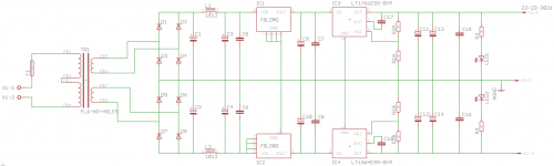
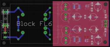
New schematic and unfinished layout are attached. Should output +/- 13.42V DC.
L1/2 = Panasonic INDUCTOR, 1812 CASE, 47.0UH
C1-4 = Panasonic FC series 35V, 470UF
C5-8 = Kemet CAPACITOR, 1206, 220NF, 50V, X7R
C17/18 = Reg BYP caps, TDK, 1206, C0G, 100V, 10NF
C9-14 = Panasonic FP series CAPACITOR, F CASE, 330UF, 25V
C15/16 = Wima Polyester 1812, 0.1UF, 63V
R1A/B = Panasonic 240R, 0805, 0.1%, 0.125W
R2A/B = Panasonic 2K4, 0805, 0.1%, 0.125W
I have now:
- Added inductors for CLC Filter
- Added holes for EI38 trafo
- Changed Regs to LT1761ES5-BYP and LT1964ES5-BYP
- Added BYP caps to regs
- Replaced trim pot with fixed resistors
New schematic and unfinished layout are attached. Should output +/- 13.42V DC.
L1/2 = Panasonic INDUCTOR, 1812 CASE, 47.0UH
C1-4 = Panasonic FC series 35V, 470UF
C5-8 = Kemet CAPACITOR, 1206, 220NF, 50V, X7R
C17/18 = Reg BYP caps, TDK, 1206, C0G, 100V, 10NF
C9-14 = Panasonic FP series CAPACITOR, F CASE, 330UF, 25V
C15/16 = Wima Polyester 1812, 0.1UF, 63V
R1A/B = Panasonic 240R, 0805, 0.1%, 0.125W
R2A/B = Panasonic 2K4, 0805, 0.1%, 0.125W
Attachments
I kinda think you will be (unpleasantly) surprised when you simulate your revised design in the frequency domain . . . . SPICE ".AC" analysis.
I kinda think SPICE will tell you that you have got a seriously underdamped resonant circuit. In addition to an unsnubbed "but I don't know what to do so I will do nothing" transformer.
I kinda think SPICE will tell you that you have got a seriously underdamped resonant circuit. In addition to an unsnubbed "but I don't know what to do so I will do nothing" transformer.
Hi I think this PSU PCB looks very good and it is well decoupled. If you will be having PCBs produced I would like to try one if possible. I have some doubt about the distance between the 230 V connector PCB pads and the mounting stud... You could use FR5 solderable fuses to avoid that. I prefer 5 x 20 fuses too but: safety first. Maybe you can move fuse holder F1 just 1 mm to the upper side and it will be fine.
* I would use smaller values for C9-C14. IMO 10 µF is better*
I kinda think that people that kinda think Spice will prove this circuit to underperform better kinda do the Spice stuff before commenting.
* I would use smaller values for C9-C14. IMO 10 µF is better*
I kinda think that people that kinda think Spice will prove this circuit to underperform better kinda do the Spice stuff before commenting.
Last edited:
Two caps 330 µF in parallel at the output is too much. Make that a single 10 to 100 µF cap. You are also using a bypass cap so why use 2 x electrolytic caps in parallel at the output ? You need capacitance at the spot where 100/120 Hz has to be buffered. So at the input.
Idea : you could use 2 x 330 µF in parallel after the rectifiers, then the coil followed by again a 330 µF cap ( for instance C9 and C10 that are now connected to the output of the 78/79Lxx). Use a 10 µF after the 78/79Lxx/before the LT regs.
Idea : you could use 2 x 330 µF in parallel after the rectifiers, then the coil followed by again a 330 µF cap ( for instance C9 and C10 that are now connected to the output of the 78/79Lxx). Use a 10 µF after the 78/79Lxx/before the LT regs.
Last edited:
Why? Just because I'm not using a snubber? Did you test it?I kinda think you will be (unpleasantly) surprised when you simulate your revised design in the frequency domain . . . . SPICE ".AC" analysis.
I kinda think SPICE will tell you that you have got a seriously underdamped resonant circuit. In addition to an unsnubbed "but I don't know what to do so I will do nothing" transformer.
Perhaps. I know it will fit but perhaps the distance needs to greater. I might make the PCB wider to accommodate some more space.I have some doubt about the distance between the 230 V connector PCB pads and the mounting stud...
Why? Can you have too much??* I would use smaller values for C9-C14. IMO 10 µF is better*
Yes, or at least something more informative than "I kinda think you will be (unpleasantly) surprised"I kinda think that people that kinda think Spice will prove this circuit to underperform better kinda do the Spice stuff before commenting.
")
Why not though? I know it might be overkill but the caps come in lots of 10 or 20 etc so I will have some spare.Two caps 330 µF in parallel at the output is too much. Make that a single 10 to 100 µF cap. You are also using a bypass cap so why use 2 x electrolytic caps in parallel at the output ?
Could do. From a technical point of view, as opposed to cost and PCB space, can you have too much uF?Idea : you could use 2 x 330 µF in parallel after the rectifiers, then the coil followed by again a 330 µF cap ( for instance C9 and C10 that are now connected to the output of the 78/79Lxx). Use a 10 µF after the 78/79Lxx/before the LT regs.
Hi, too much µF after conventional regs will make them oscillate as the ESR will become too low for the reg to function properly. Google for the exact technical explanation. Check datasheet of 78Lxx for max. capacitance after the reg. Recent LDO's are more tolerant but why would you use much µF ? They don't need to filter 100 Hz at their outputs (rectified 50 Hz AC will be 100 Hz pulsating DC). The input caps buffer the ripple of the pulsating DC voltage. At that spot you want good filtering of ripple and other stuff you need to get rid of.
Rule of thumb (can be calculated) is about 2000 µF per Ampere load current for 1 V ripple. Old info that was learnt many years ago. I am not the only one using the rule of thumb. It is way easier to keep in the head than the actual calculation
http://lenardaudio.com/education/12_amps_7.html
I would use around 1000 µF in total for 100 mA load but 2200 µF is standard value and can be used too with the drawback that those will be higher than 3 x 330 µf. Ripple will be very low and total voltage will be way above the minimum required voltage for correct working of the 78/79Lxx. Much larger value won't bring benefits. The coils will filter RF/HF and the regs don't need to do much work except for being preregs for the LT's.
Last edited:
Not wanting to overcomplicate, but I've gotten very interested in methods of calculating PSU and decoupling cap values, lately (for the last year or so). What type of load will this PSU be powering? Do you have any specs for the load? Are there any dynamic requirements for the output voltage and current?
i.e. If it will be an active load, what is the minimum voltage between the power rail and the output (the active device's "vclip" voltage, e.g. a few volts, for a transistor output stage), and what is the desired maximum signal voltage swing at the output of the load, and what impedance is the active load driving? Those might enable calculating the maximum ripple voltage at the onset of clipping, or load device "dropout", which would be caused by the load current drawing down the output caps' voltage. Is there a "maximum tolerable ripple" spec at the load output? Actually, with the regulator(s) there, I would probably have to just simulate the circuit as a whole. But that would be interesting, too. (Worst case would be to simulate with constant DC current that's equal to peak of output current swing, with long-period square waves.)
i.e. If it will be an active load, what is the minimum voltage between the power rail and the output (the active device's "vclip" voltage, e.g. a few volts, for a transistor output stage), and what is the desired maximum signal voltage swing at the output of the load, and what impedance is the active load driving? Those might enable calculating the maximum ripple voltage at the onset of clipping, or load device "dropout", which would be caused by the load current drawing down the output caps' voltage. Is there a "maximum tolerable ripple" spec at the load output? Actually, with the regulator(s) there, I would probably have to just simulate the circuit as a whole. But that would be interesting, too. (Worst case would be to simulate with constant DC current that's equal to peak of output current swing, with long-period square waves.)
Last edited:
I welcome the complication Gootee! But remember, I have no measuring equipment beyond a simple multimeter.
The LT regs only do 100mA max. I plan to use it to power OPAMP based circuits like a simple linestage, PGA2320, CS3318 or my R2R DAC attenuator.
What values would you recommend in my design?
The LT regs only do 100mA max. I plan to use it to power OPAMP based circuits like a simple linestage, PGA2320, CS3318 or my R2R DAC attenuator.
What values would you recommend in my design?
Sorry. I was helping a friend do plumbing and electrical repairs and upgrades all day and evening and have to get up early. But I will try to tackle some simulations tomorrow evening!
I don't expect any major differences from what jean-paul suggested. But it's more-interesting than the simplest types of regulated and unregulated supplies and I will like seeing how the variables in each stage affect the other stages and the output.
I don't expect any major differences from what jean-paul suggested. But it's more-interesting than the simplest types of regulated and unregulated supplies and I will like seeing how the variables in each stage affect the other stages and the output.
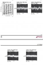
That data is for noise, which is different from ripple. So far I am mostly evaluating the ability to deliver transient currents, and how that affects the output voltages, for ranges of various component values. I will upload the LT-Spice model, later, for anyone else who wants to play with it.
While we wait for Gootee's results, I have some more questions...
Someone has kindly offered to measure my transformer using transistormarkj Quasimodo test-jig so I'll include places for snubber components. Also then if anyone else wants to use this design they can add a snubber too.
So I have some questions are around Cx, Cs and Rs components so I know what package sizes to add:
1. Is 0.25W enough for Rs? Or 0.5W? What resistor element types are usable? Thick film? Thin? Metal?
2. Are PEN and PET type film caps OK for Cs and Cx? If so I'll include pads for 1206/1812 caps.
3. Is it possible or desirable to use a snubber on the trafo secondaries AND the CLC filter?
4. I've seen on many power supply PCBs one corner will have a conductive pad around the screw hole to connect GND to the chassis via the stud/stand-off. Should I include this too? Just a straight connection to GND?
You can either use math, or circuit simulation, to find the power dissipated in Rsnub. (Quasimodo design note, p.7) Then select a resistor rated for 2X or 4X that amount of power.
Choose a resistor type whose impedance remains resistive (i.e. Im(Z) = 0, or if you prefer, Phase(Z) = 0) up to at least 10 MHz, since you're snubbing an RLC resonant circuit whose natural frequency omega_n can be as high as 3 or even 7 MHz. Folklore and ancient mythology suggest that carbon composition resistors are the best choices for snubbing, and I imagine they only get better when you anoint them with olive oil, frankincense, and myrrh before soldering. Storing them overnight under a balsa wood pyramid and burning a couple of patchouli sticks might bring further benefits.
Capacitor types with very low dissipation factors (tan δ ≤ 0.01) are preferred for Cx and Csnub (Quasimodo design note, p.7). You want Re(Z) as close to zero as possible. Check the datasheets for tan δ.
If you're going to add a second snubber at the output of your CLC filter, it may be prudent to perform lowZ pulse gen ("bell ringer") testing more than once. It might give you additional peace of mind, to know that adding snubber2 doesn't radically change the optimum values of snubbber1, and vice-versa. In other words, to verify that they don't screw each other up.
OK thanks transistormarkj. You disabled copy/paste in your App note PDF file (why?!?), so I won't quote it word for word, but...
You say that generally for voltages less than 75 volts when Rs is between 50R and 500R the dissipation will be less than 70 mW. So I think 1206 pads and a 0.250mW resistor will be fine for this PSU. You also mention you use metal film and they are plentiful in 1206.
You mention using metallised film caps but not specifically which types. PET and PEN are both types but according to wikipedia, they have somewhat different dissipation factor. I have no idea what is a low value for this or not. Can I assume that Wima SMDT series caps are OK?
Thanks for your help!
Do they have tan δ ≤ 0.01 ? If so, I think you'll probably be ok.
Ah I get you now. For that WIMA cap, yes they do but only at low frequencies..
1 kHz: 8 x 10^-3 (= 0.008)
10 kHz: 15 x 10^-3 (= 0.015)
100 kHz: 30 x 10^-3 (= 0.030)
Suitable or not?
I also checked a datasheet for an AVX "PEN DIELECTRIC – CB Series" cap it has 0.0075 up to about 100khz.
- Status
- This old topic is closed. If you want to reopen this topic, contact a moderator using the "Report Post" button.
- Home
- Amplifiers
- Power Supplies
- A simple but low noise LT1761/LT1964 PSU design