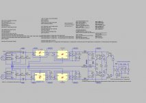
Attached is a zip file with two LT-Spice circuits and the necessary files for them. One uses LT1964 and LT1962. The other uses LT1964 and LT1761.
Attachments
Last edited:
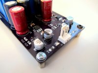
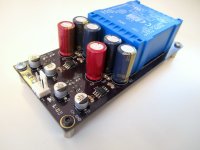
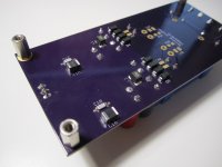
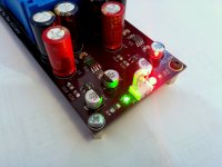
And built! Works perfectly.
I used R1 of 240R and R2 of 2400R to give +/- 13.4V. It's about 35mm tall with standoffs so will fit in a 1U enclosure nicely.
I have 2 spare PCBs if anyone is interested.
I used R1 of 240R and R2 of 2400R to give +/- 13.4V. It's about 35mm tall with standoffs so will fit in a 1U enclosure nicely.
I have 2 spare PCBs if anyone is interested.
Attachments
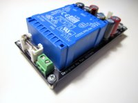
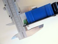
Excellent photos! And a very lovely build, with SMD resistors aligned much better than I usually achieve! Protip: calipers with electronic digital readouts are now very inexpensive
example #1
example #2
example #3
example #1
example #2
example #3
Excellent photos! And a very lovely build, with SMD resistors aligned much better than I usually achieve! Protip: calipers with electronic digital readouts are now very inexpensive
example #1
example #2
example #3
Thanks Mark! I actually prefer the non-digital calipers, is that strange??
Very nice job, maxw. A pleasure to see the build quality in the very nice pictures.
Thanks Karsten.
Please look over my Eagle Conversion to 120Volts
Attached is my first trail to convert of your 240-Volt Dual Power Supply Eagle files to 120-Volt Dual Power Supply Eagle files. I know NOTHING about Eagle. This is the first time I have try using Eagle, so please forgive me for ant mistakes. Let me know what you think of my attempt to make the necessary changes.
Attached is my first trail to convert of your 240-Volt Dual Power Supply Eagle files to 120-Volt Dual Power Supply Eagle files. I know NOTHING about Eagle.
This is the first time I have try using Eagle, so please forgive me for ant mistakes. Let me know what you think of my attempt to make the necessary changes.Attachments
Hi mrsavage,
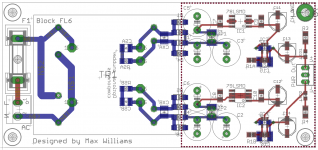
Yeah it looks OK, it will work. Note that N$2 trace doesn't fully connect to the top middle/bottom pad of the transformer.
But if I was you, I would modify my TPS7A3301 PSU instead of the one in this thread.
Yeah it looks OK, it will work. Note that N$2 trace doesn't fully connect to the top middle/bottom pad of the transformer.
But if I was you, I would modify my TPS7A3301 PSU instead of the one in this thread.
Attachments
Last edited:
- Status
- This old topic is closed. If you want to reopen this topic, contact a moderator using the "Report Post" button.
- Home
- Amplifiers
- Power Supplies
- A simple but low noise LT1761/LT1964 PSU design