Yeah, I get that -- if you are using an 1N4007 or a MUR860, MBR20100 it might be interesting to know what is going on and why.
After determining the correct/appropriate value of Rs and Cs for a little Hammond 12VA EI trafo, using a common ST bridge rectifier, and putting them into a real world circuit I see no before/after effect. Nor can I see any harmonics when snooping the circuit with my HP 3577a in either case. I suppose that in audio circuits, in this case a line amplifier, the circuit faces a relatively constant output impedance which sufficiently damps the switching ringing of the diode (granted that these ST bridges aren't the fastest greyhound in the kennel).
After determining the correct/appropriate value of Rs and Cs for a little Hammond 12VA EI trafo, using a common ST bridge rectifier, and putting them into a real world circuit I see no before/after effect. Nor can I see any harmonics when snooping the circuit with my HP 3577a in either case. I suppose that in audio circuits, in this case a line amplifier, the circuit faces a relatively constant output impedance which sufficiently damps the switching ringing of the diode (granted that these ST bridges aren't the fastest greyhound in the kennel).
Jack, the switching ringing in a practical power supply may not be observable, especially if the diode on-to-off transition is very mild in terms of the change in dI/dt seen by the PT winding leakage inductance. In the bell-ringer circuit Mark ensures the winding is hit as hard as practically possible. In practise, the rectifier diode may be turned off from such a low value of peak current (eg. in a preamp), and the winding has sufficient shunt capacitance and resistance, that any disturbance is benign. Whatever the diode used, there would be effectively no reverse recovery related effect, and a pn junction would just sedately fall through its on-voltage and the junction diffusion capacitance just fall down to reverse-bias levels as Qrr is relatively so small.
@trobbins -- thanks! I guess my interest is probably academic -- Mr. Modo would seem to be a great tool to teach undergrads the real world of electricity and magnetism.
The way I had done it before was to measure the inductances open, measure the inductances short, and measure the "transmission" or gain. From this you can determine the coupling ratio and the leakage inductance falls out of the equations. Mark's tool makes it much easier!
The way I had done it before was to measure the inductances open, measure the inductances short, and measure the "transmission" or gain. From this you can determine the coupling ratio and the leakage inductance falls out of the equations. Mark's tool makes it much easier!
The interesting aspect for modelling such a system would be the model given to the diode capacitance part of CT. For the bell-ringer circuit, any such diode capacitance is assumed constant. For modelling an actual power supply's response, the diode junction capacitance would need to be non-linear (possibly a topic only for later year undergrads or post-grads).
Given the diode's on-to-off voltage transition region is when the junction has a slight positive bias, the typically found diode datasheet capacitance curves don't go far enough in identifying what could be a diffusion capacitance level for the junction - I have seen that characteristic capacitance explored in a few research papers.
Given the diode's on-to-off voltage transition region is when the junction has a slight positive bias, the typically found diode datasheet capacitance curves don't go far enough in identifying what could be a diffusion capacitance level for the junction - I have seen that characteristic capacitance explored in a few research papers.
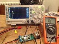
I built a Quasimodo and attempted to use it for the first time.
I'm testing a dual-primary/dual-secondary AnTek toroidal transformer.
Shorted each primary winding and one secondary separately.
The remaining secondary was connected to the Quasimodo.
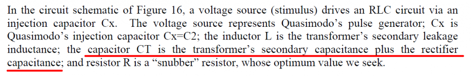
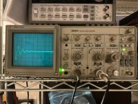
I'm fairly novice at using an Oscilloscope so it took me a very long time to get the triggering working.
After going through the process in the PDF, the resistor read 31ohms for both sides.
Does that sound like a reasonable result?
I attached screenshots of the scope with inf.R and 31R.
I'm testing a dual-primary/dual-secondary AnTek toroidal transformer.
Shorted each primary winding and one secondary separately.
The remaining secondary was connected to the Quasimodo.
I'm fairly novice at using an Oscilloscope so it took me a very long time to get the triggering working.
After going through the process in the PDF, the resistor read 31ohms for both sides.
Does that sound like a reasonable result?
I attached screenshots of the scope with inf.R and 31R.
Attachments
The interesting aspect for modelling such a system would be the model given to the diode capacitance part of CT. For the bell-ringer circuit, any such diode capacitance is assumed constant. For modelling an actual power supply's response, the diode junction capacitance would need to be non-linear (possibly a topic only for later year undergrads or post-grads).
Given the diode's on-to-off voltage transition region is when the junction has a slight positive bias, the typically found diode datasheet capacitance curves don't go far enough in identifying what could be a diffusion capacitance level for the junction - I have seen that characteristic capacitance explored in a few research papers.
Fortunately the design committee who created Quasimodo was aware of these second order concerns. And that is why paragraph 4 of page 5 was written: it discusses the hardware design solution to these annoyances.
Does that sound like a reasonable result?
Search the "Power Supplies" forum for a discussion thread whose name is "Quasimodo Results (ONLY)".
See whether you can find similar transformers mentioned. See whether their results are "reasonable" congruences to your results.
If even a newbie like me can do this?
Me too. It took me one day to remove the 2 chips I had installed backwards, and resolder new ones. The LED is bright green now.
Took me all afternoon to remember how to hook up the scope. It's been years since I used it.
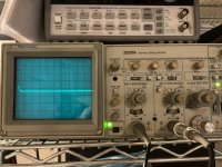
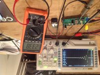
The transformer is an Antek 3222, with C2 and C3 values of .001 and .15uF respectively. Will post all details on the results thread after I run the other secondary.
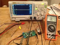
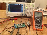
The first photo show the waveform with no RV1 in the socket (upside down, not sure why?) Then photo2 with a few turns at 64.8r, photo3 shows what I thought was good at 19.1r, then the last one Photo4 (did I go too far?) at 9.0r.
I guess I feel that a resistor with value between 9 and 19 ohms should do the trick to dampen the waveform unless I hear otherwise from the experts on the thread, or the other secondary gives me wildly unexpected results.
Thank you Mark for making this accessible to someone with as little experience as me!
Sixto
I built a Quasimodo and attempted to use it for the first time.
.
Me too. It took me one day to remove the 2 chips I had installed backwards, and resolder new ones. The LED is bright green now.
Took me all afternoon to remember how to hook up the scope. It's been years since I used it.
The transformer is an Antek 3222, with C2 and C3 values of .001 and .15uF respectively. Will post all details on the results thread after I run the other secondary.
The first photo show the waveform with no RV1 in the socket (upside down, not sure why?) Then photo2 with a few turns at 64.8r, photo3 shows what I thought was good at 19.1r, then the last one Photo4 (did I go too far?) at 9.0r.
I guess I feel that a resistor with value between 9 and 19 ohms should do the trick to dampen the waveform unless I hear otherwise from the experts on the thread, or the other secondary gives me wildly unexpected results.
Thank you Mark for making this accessible to someone with as little experience as me!
Sixto
Attachments
Hi itsikhefezz,
I'm not as experienced with the Tek 2235 as some of the folks here, but I did notice a couple things ..
- some of the trigger challenges could be from using the B trace -- that requires adjusting 2 thresholds, plus holdoff; B sweep is really for another test situation altogether
- it might help if you stick to DC coupling 'til you're more comfortable -- especially with a low-duty-cycle signal (as this is)
- probably just a personal preference of mine, but I keep the Var knobs in the CAL position, except for special instances -- it has saved me a misleading *measurement* more than once
Overall it's looking pretty good to me ..")
Is this a great piece of kit, or what?! Thanks M J
Cheers
I'm not as experienced with the Tek 2235 as some of the folks here, but I did notice a couple things ..
- some of the trigger challenges could be from using the B trace -- that requires adjusting 2 thresholds, plus holdoff; B sweep is really for another test situation altogether
- it might help if you stick to DC coupling 'til you're more comfortable -- especially with a low-duty-cycle signal (as this is)
- probably just a personal preference of mine, but I keep the Var knobs in the CAL position, except for special instances -- it has saved me a misleading *measurement* more than once
Overall it's looking pretty good to me ..
Is this a great piece of kit, or what?! Thanks M J
Cheers
Last edited:
Follow-up
Testing the other secondary (V-) gave me similar results (within 2r), so that's good. I also moved the probes from a pin inserted into the empty sockets spots at c2 to c3 and results were the same. The DIP switches made some difference to the waveforms after I adjusted the scope to maximize visibility, but not enough to change the results. So I'm Going to split the difference and get some 15 ohm resistors for both secondary snubbers. Fun stuff!
Sixto
The transformer is an Antek 3222, with C2 and C3 values of .001 and .15uF respectively. Will post all details on the results thread after I run the other secondary....
... a resistor with value between 9 and 19 ohms should do the trick to dampen the waveform unless I hear otherwise from the experts on the thread, or the other secondary gives me wildly unexpected results.
Testing the other secondary (V-) gave me similar results (within 2r), so that's good. I also moved the probes from a pin inserted into the empty sockets spots at c2 to c3 and results were the same. The DIP switches made some difference to the waveforms after I adjusted the scope to maximize visibility, but not enough to change the results. So I'm Going to split the difference and get some 15 ohm resistors for both secondary snubbers. Fun stuff!
Sixto
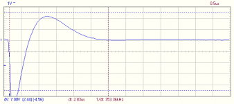
Custom shielded transformer Pri:240V, Sec: 22V-0-22V
Hi guys,
After many year i finally got down to building and using the Quasimodo. I used Cx=10nF, Cs = 150nF.
While I managed to fine tune and got a waveform with Zeta = 1 with Rs of 36ohm to 40ohm, the second peak level was still almost 2V, is that a cause for concerns. Does that means i need to tweak the Cx or Cs values?
Alex
Attachments

Experienced Quasimodo users, and/or power transformer snubbing experts, are invited to view, and reply to, a member's question on the CheapoModo thread. If you decide to make a reply, please do so on that thread. The wisdom of crowds is a powerful force.
CheapoModo post #333
CheapoModo post #333
- Home
- Amplifiers
- Power Supplies
- Simple, no-math transformer snubber using Quasimodo test-jig