You short the primaries to properly excite and measure the electrical ringing of the transformer.
Yes, 10ohm is reasonable. For example, the Antek transformers used in the Pass amps have been about 18-22ohm.
If I need Rs to be 10 ohms and my transformer secondary is putting out 9.6Vac RMS, then:
V = I * R
9.6Vac = I * 10 ohms
I = 0.96 amps!
The current passsing through my 10 ohm Rs will be 0.96 amps and I will need at minimum a 10 watt resistor...
Yikes!
It will also run my transformer a lot warmer.
Is this all correct?
I see Cs is in series with Rs - how much voltage is dropped across Cs? I would think very little.
Is it posssible to change the values of Cx and/or Cs to get a higher value of Rs? I tried this quickly and it did not seem to do much.
Last edited:
Here is the math to calculate power dissipated in the snubber resistor. It is typical of a homework problem given to 2nd year EE undergraduates taking their first Circuit Analysis class.
Click on the blue arrowhead to be transported to that post, which includes all the math in a 1-page .pdf document. It is #1358 of this thread.
Click on the blue arrowhead to be transported to that post, which includes all the math in a 1-page .pdf document. It is #1358 of this thread.
Thank you Mark!
I did the manual calculation and also did LT Spice and both gave me 3 x 10⁻⁶ Watts.
Or basically nothing!
Sweet!
It's good to know that ltspice says the same as your math. I thought I was wrong somewhere because I got 8.6E-7 W(I don't have ltspice)Thank you Mark!
I did the manual calculation and also did LT Spice and both gave me 3 x 10⁻⁶ Watts.
Or basically nothing!
Sweet!
Transformer 18v on secondary
f = 50
Rs 12R
I looked for suitable diodes/bridge for a 2kVA transformer feeding a large bank of caps
(230/2x46V, primary Rdc 0,47ohm!) and came across this:
STPS200170TV1
at least 700pF typical junction capacitance at 130V reverse voltage
at least 7000pF at 1V !!!
I have some BYW93/200 that should handle the task but I have no data on capacitance and I would like something easier to mount/cool than 4 diodes in DO5 package.
Has anyone any idea what the junction capacitance of fast/soft recovery 200V rectifier diodes with at least 600A/10ms/100degC surge-current rating and low forward voltage drop would be?
Last edited:
Maybe you could look at these datasheets, find the subset which interests you, and calculate the mean and the standard deviation of zero-bias junction capacitance (?)
- MBR40250 schottky
- APT30S20B schottky
- APT50S20B schottky
- FFH60UP40 ultrafast recovery
- STTH6004W ultrafast recovery
If you get no replies from diyAudio members after a few days (remember it's the holidays), you can try this Google search. Hit #1 lists €9.00
quasimodo pcb price - Google Search
quasimodo pcb price - Google Search
About Quasimodo
Hello Mark, hello all,
Sorry to all for my basic English......
I have try to learn and understand all about your Snubber calculate via your Quasimodo
I have search and buy a used Oscilloscope FLUKE PM3394
I have buy in this forum a good Quasimodo V4
And after a long périod to learn Oscillo.
I started to take measurements on transformers
Transformer was a 120VA(TOROIDY-SUPREME-AUDIO-GRADE-V2)....primary was 220v.....only one secondary was 20v
CH1=10v
CH2=5v(or 2v)
For obtain Zeta(ζ)=1 the résistor was 34.90 Ω
For Cs(C3)=100 or 150 or 220 nF the résult was the same, and the response curve is the same.....correct?
With Cx(C2)=10 nF and powered by a battery 9v
......I think until everything seems correct......
However I noticed something, in beginnig of this measure the résistor was 36.95 Ω
After one hour, two and three hours the value fell to 34.90 Ω
have you ever noticed this phenomenon...?
the PCB Quasimodo V4 does he need to heat..?
Thanks for all your works
And happy new year to all
Charles
Attachments
Hiiii Mark,
Thanks to your answer.
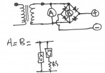
Now, for snubber implementation
What are the best implementation
A or B or other..??
In your opinion what type of diode would be the best..
I have
.HEXFRED:
.VS-HFA25TB60-M3 -VISHAY, 600 V, 25 A, 1.7 V, 75 ns, 225 A, TO-220
.SCHOTTKY:
.MBR40250G -ON SEMICONDUCTOR, 250 V, 40 A, 35 ns, TO-220
.DSA30I150PA-IXYS-Schottky Diode Gen ², 150 V, 30 A, 10 ms, TO-220
. Avalanche Type:
.IXYS-VBO25-16A02, 1600 V, 38 A
Or others
Regards
Thanks to your answer.
Now, for snubber implementation
What are the best implementation
A or B or other..??
In your opinion what type of diode would be the best..
I have
.HEXFRED:
.VS-HFA25TB60-M3 -VISHAY, 600 V, 25 A, 1.7 V, 75 ns, 225 A, TO-220
.SCHOTTKY:
.MBR40250G -ON SEMICONDUCTOR, 250 V, 40 A, 35 ns, TO-220
.DSA30I150PA-IXYS-Schottky Diode Gen ², 150 V, 30 A, 10 ms, TO-220
. Avalanche Type:
.IXYS-VBO25-16A02, 1600 V, 38 A
Or others
Regards
Attachments
Simple, no-math transformer snubber using Quasimodo test-jig
Charly, there's your answer. You are snubbing the transformer not the diodes. Therefore: locate the snubber as close to the transformer as is reasonably possible. Pragmatically speaking, that's probably on the same PCB as the diodes.")
Diode choice is a matter of personal preference mostly; choose whichever ones your wife likes most, or whichever ones will impress your audiophile friends most, or whichever are cheapest and available at your favorite diode seller, etc. Soft recovery diodes are a little better, but once you use a snubber to achieve zeta=1.0 damping, all diodes become equally pitiful bell-ringers. They all provoke the same amount of ringing: zero!
I've just closed out a Group Buy of a power supply PCB designed to drive two LM3886 chip amps (40W per channel into 8 ohms), its schematic is attached to post #1719 of this thread. For that chipamp application I chose Schottky diodes, because I wanted them to run as cool as possible. Diode power dissipation is (I_load x V_diode_fwd), and the power supply designer has no control over I_load. So the only thing left to do is pick a diode with very low V_diode_fwd. That's what I did: I chose the MBR10100G. It's "only" 10 amps and "only" 100 volts, which may not be big enough numbers for your needs.
_
Charly, there's your answer. You are snubbing the transformer not the diodes. Therefore: locate the snubber as close to the transformer as is reasonably possible. Pragmatically speaking, that's probably on the same PCB as the diodes.
Diode choice is a matter of personal preference mostly; choose whichever ones your wife likes most, or whichever ones will impress your audiophile friends most, or whichever are cheapest and available at your favorite diode seller, etc. Soft recovery diodes are a little better, but once you use a snubber to achieve zeta=1.0 damping, all diodes become equally pitiful bell-ringers. They all provoke the same amount of ringing: zero!
I've just closed out a Group Buy of a power supply PCB designed to drive two LM3886 chip amps (40W per channel into 8 ohms), its schematic is attached to post #1719 of this thread. For that chipamp application I chose Schottky diodes, because I wanted them to run as cool as possible. Diode power dissipation is (I_load x V_diode_fwd), and the power supply designer has no control over I_load. So the only thing left to do is pick a diode with very low V_diode_fwd. That's what I did: I chose the MBR10100G. It's "only" 10 amps and "only" 100 volts, which may not be big enough numbers for your needs.
_
Last edited:
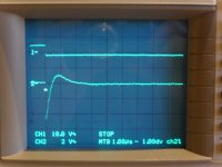
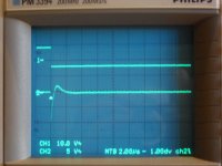
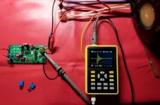
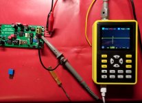
Mark, thanks for this nice Quasimodo test-jig !
It works great.
My 2nd scope is a very cheap handheld one,
surprisingly it's also usable with your test-jig.
Pic1: infinity resistance
Pic2: 10 ohm
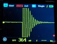
Pic3: infinity resistance, v zoomed in
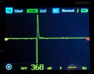
Pic4: 10 ohm, v zoomed in
Thanks to the dipswitch to select the oscillator freq I could locate a resonance on the cheap one channel scope.
The transformer is a Toroidy 230v/2x18v 400VA
It works great.
My 2nd scope is a very cheap handheld one,
surprisingly it's also usable with your test-jig.
Pic1: infinity resistance
Pic2: 10 ohm
Pic3: infinity resistance, v zoomed in
Pic4: 10 ohm, v zoomed in
Thanks to the dipswitch to select the oscillator freq I could locate a resonance on the cheap one channel scope.
The transformer is a Toroidy 230v/2x18v 400VA
Attachments
Last edited:
Congratulations, danny_66! You've got excellent damping in the "after" pictures. Maybe you would enjoy the waveforms even more, with a faster horizontal sweep rate, such as perhaps 1 microsecond per division or even 500 nanoseconds per division. If your scope will sweep that fast and if it will correctly trigger!
My own experiments with the $19 "DSO-138" oscilloscope kit were a disaster: post #846
My own experiments with the $19 "DSO-138" oscilloscope kit were a disaster: post #846
- Home
- Amplifiers
- Power Supplies
- Simple, no-math transformer snubber using Quasimodo test-jig