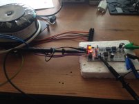
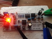
Back in France and ready to use my Quasimodo, thanks to diyAudio member "yoaudio" for the board and "SyncTronX" for the Mosfet (NTD4906). I Just try today with couple of tranfo and this is really easy to use.
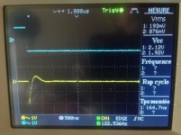
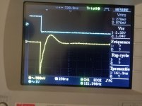
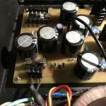
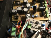
After practicing that is the result for my new Toroidy custom transformer 450va 240v with 2 X 25v (8A), 24v (1A), 12v (1A), 7v(1A)
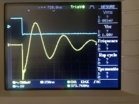
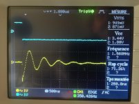
Picture #3 - #4 same and #5 - 6 same with a different oscilloscope setting.
Cx 10nF
Cs 150nF
Rs 15Ω
Marc i have a question for you may be it is ridiculous ....but a couple of time you refer to Zeta =1 or =0.5 or an other value.
What is Zeta ???
After practicing that is the result for my new Toroidy custom transformer 450va 240v with 2 X 25v (8A), 24v (1A), 12v (1A), 7v(1A)
Picture #3 - #4 same and #5 - 6 same with a different oscilloscope setting.
Cx 10nF
Cs 150nF
Rs 15Ω
Marc i have a question for you may be it is ridiculous ....but a couple of time you refer to Zeta =1 or =0.5 or an other value.
What is Zeta ???
Attachments
Zeta is the greek letter that denotes the damping ratio. For those who aren't thoroughly familiar with the mathematics of control systems, I recommend always using Zeta=1.00, a magical value which textbooks call "Critical Damping". People who really really know what they are doing, can choose their own value of zeta and can operate a little closer to THE CLIFF OF IMMEDIATE PAINFUL DEATH. Unlike beginners, experts know the risks.
Zeta is discussed on page #1 of the Quasimodo instruction manual, which is a .pdf attachment on the very first post in this thread.
Zeta is discussed on page #1 of the Quasimodo instruction manual, which is a .pdf attachment on the very first post in this thread.
I have to order some boards for my own DIY and i was thinking may be if i order also 10 Quasimodo v4 through hole boards, that will not cost me more, i have to paid the shipping for my boards all ready, so may be some of you are interested, I will have this boards available for free for European residents.
If you live in another country, you could probably get 10 boards from the manufacture for the price it would cost me to ship it to you . "first come first serve", PM please with your mailing address.
If you live in another country, you could probably get 10 boards from the manufacture for the price it would cost me to ship it to you . "first come first serve", PM please with your mailing address.
Attachments
I just tested an Acoustat high voltage power supply transformer, with Cx = 10nF and Cs = 100nF and found the optimal value of Rs to be 4.7K. This transformer has a 750 volt secondary, so it makes some sense that the Rs value would be higher than for a lower voltage higher current transformer, so hopefully this is correct.
I was forced to use 100nF for Cs as it is very difficult to find a full range of values for capacitors with a sufficient AC voltage rating for this transformer. For Rs I am planning on using a 2 watt carbon composition resistor, but I could easily use a 5 or 10 watt part here instead. For Cx I have chosen this capacitor:
PHE450XD5100JD15R06L2 KEMET | Mouser Canada
And for Cs this capacitor:
B32656S2104J564 EPCOS / TDK | Mouser Canada
Does all of this look reasonable? I don't believe that anyone has tried to add snubbers to this type of transformer yet, so I'm not sure exactly what to expect or any possible pitfalls from things that I have failed to consider. I'm very interested to see what if any difference this will make to the sound and how it compares to putting snubbers in my preamplifiers and power amplifiers, so I'm very interested in feedback and suggestions.
Take care,
Doug
I would not recommend (Cs / Cx) less than 15, as you have it here. However I imagine you do not wish to spend another 21 dollars to increase Cs. So you may be economically forced into a situation where you say "who cares about the math, the scope trace looks good to me, and I'm copying THESE EXACT PARTS into the final electronic product. Quasimodo is testing THE EXACT PARTS I will use in my product. The scope trace I see on Quasimodo, is acceptable to me."
When you're coughing up the money to buy these components you might find comfort in the observation that it's certainly better than no snubber at all.
When you're coughing up the money to buy these components you might find comfort in the observation that it's certainly better than no snubber at all.
Thanks for the comments, Mark.
I was going by your application note which indicated that the ratio should be between 10 and 20 times. I can certainly use two of the 100nF capacitors, making the ratio 20 instead of 10, if it will make a difference in how effective the snubber is. It's not so much the price as it is the space that I have available, but I think that I can deal with that. The quasimodo waveforms did look fine to me, just the same as all the other transformers that I have tested with your preferred capacitors. However, I really don't want to compromise performance for the sake of one capacitor.
Take care,
Doug
Can't see your pic.
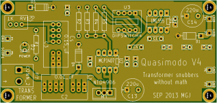
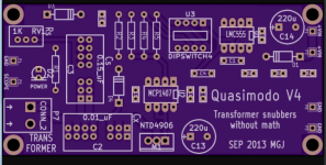
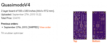
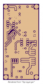
Luckily, OSH Park kept the files on their server from when I ordered Quasimodo V4 boards back in 2013 (!). Here is what I see on OSH Park's website.
These are not photographs, they are computer generated "renderings" of what the finished PCBs will look like after fab. If all goes according to plan.
_
Attachments
Last edited:
Looks right.
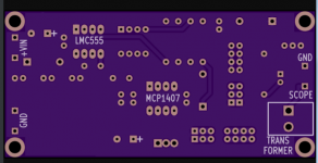
Quasimodo V4 PCB uses a "flood / fill" to reduce the VHF impedance of its power and ground network. The top (component) side of the board is flooded to approximate a power plane, and the bottom (solder) side is a ground plane. Why? Because it's got > 100mA current pulses with 1.5 nanosecond rise time. Smells like VHF to me. (This is why I encouraged member EUVL to solder the MCP1407 directly into the PCB with no socket. But he declined.)
Quasimodo V4 PCB uses a "flood / fill" to reduce the VHF impedance of its power and ground network. The top (component) side of the board is flooded to approximate a power plane, and the bottom (solder) side is a ground plane. Why? Because it's got > 100mA current pulses with 1.5 nanosecond rise time. Smells like VHF to me. (This is why I encouraged member EUVL to solder the MCP1407 directly into the PCB with no socket. But he declined.)
So I have experimented with different values of Cs, and have found that I need to go a bit smaller than 100nF to get any significant apparent change in the performance of the snubber. Using 47nF definitely makes things visibly worse and any smaller value significantly compromises the snubber's performance.
Going the other way, 200nF makes for a very slight increase in the peak of the positive part of the correctly damped Quasimodo waveform, and using 1uF also results in another very slight change. Any increase after that makes no difference at all that I am able to discern. As far as I can tell the snubber appears to work quite effectively with any Cs value of 100nF or greater.
When I started the process of installing the parts in the Acoustat interface, I found that there was really no room at all for adding a second 100nF capacitor for Cs anyways, and since the single capacitor appeared to perform very well in my tests, I decided to go with my original plan of 100nF for Cs, 10nF for Cx, and 4.7K for Rs.
I did the math for the resistor power dissipation and came up with a figure of 3.64 watts. Based on that calculation I ended up using a 10 watt resistor to give a good safety margin. In use I found that this resistor gets fairly warm but not so hot that you can't hold your finger on it, so I was satisfied with that choice, and installed the snubbers into the bias supplies of a pair of Acoustat 1 + 1 speakers.
My expectations were fairly low for how much this modification would actually affect the sound, but I was pleasantly surprised with the results. Both my wife and I heard big improvements in the music similar to our experiences with adding Quasimodo snubbers to other signal-chain components.
Thanks again to Mark for sharing this fantastic invention and for taking the time to help us to understand and use it. I have now installed optimised snubbers in every linear power supply in my system, and the difference in sound quality is truly amazing!
Take care,
Doug
Congratulations Doug! Glad to know you found a way to make it work to your satisfaction, in a super high voltage power supply. Be sure to double check the temperature of Cs too; in some HV cases it might get warm.
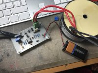
It's just delightful to hear that snubbing out any and all possible transformer secondary ringing, had such a positive effect upon listening enjoyment! The modest little test jig with its scrawny 9V battery flopping around on the side, really did make an improvement. Woo hoo, science works.
It's just delightful to hear that snubbing out any and all possible transformer secondary ringing, had such a positive effect upon listening enjoyment! The modest little test jig with its scrawny 9V battery flopping around on the side, really did make an improvement. Woo hoo, science works.
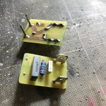
My first attempting
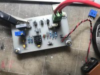
Hi, this is my first attempting with my DIY Cheapomodo PCB (1 side toner transfer…). What do you think about the result. 50 Ohm is right? I use 500 ohm trimmer for best reading.
Thanks…
Hi, this is my first attempting with my DIY Cheapomodo PCB (1 side toner transfer…). What do you think about the result. 50 Ohm is right? I use 500 ohm trimmer for best reading.
Thanks…
Attachments
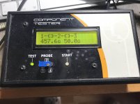
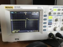
Scope photo (#3) looks perfect!
Also congratulations on laying out and fabricating your own PCB! Not many diyAudio members are as bold as you. The non-CMOS-555-chip oscillator used in Cheapomodo, doesn't work at super low voltage supplies (3V). But as long as you use a 9V battery, that won't make any difference at all.
Also congratulations on laying out and fabricating your own PCB! Not many diyAudio members are as bold as you. The non-CMOS-555-chip oscillator used in Cheapomodo, doesn't work at super low voltage supplies (3V). But as long as you use a 9V battery, that won't make any difference at all.
Hi, thanks for the compliment ...
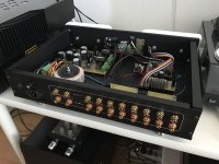
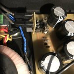
This is my little snubber module that I inserted in my BOZ Nelson Pass preamp. Can this solution work, are there any contraindications?
Bye…
This is my little snubber module that I inserted in my BOZ Nelson Pass preamp. Can this solution work, are there any contraindications?
Bye…
Attachments
- Home
- Amplifiers
- Power Supplies
- Simple, no-math transformer snubber using Quasimodo test-jig