I would like to say big thank you to Mark Johnson for making the Quasimodo test jig design available! I just snubbed two identical 6VA, 6V+6V block transformers and am really happy with how it worked. It really is a lot of fun seeing the waveform changing as you turn the trimpot ")
Regards,
Oleg
Regards,
Oleg
Congratulations on your success, Oleg! Next time you've got your QM board running on the bench, driving a transformer, take a couple of scope photos: Before (with Rx trimpot removed from the socket thus Infinity ohms), and After (with Rx adjusted for good zeta=1 damping).
Attaboy and Good On Ya.
Attaboy and Good On Ya.
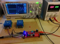
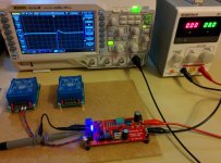
Beautiful! There's an engineer who thinks for himself -- notice that he's running his Quasimodo at +8.0 volts. Not 15 volts, not 10 volts, not 9 volts, not 5 volts. 8.0 volts (!). Good show. Also notice that the negative edge in the left photo is exactly 4 divisions tall times 2 volts per division: 8.0 volts. Science!
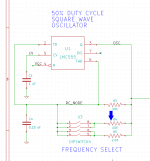
I think you will discover that your Quasimodo works beautifully when you close the DIP switch that inserts resistor "R4" in parallel with "R3". Try it. Now measure the frequency of oscillation in this condition. I think you will discover it is approximately 600 Hertz.
Now ask yourself: if my very own Quasimodo works well, right here in my home, when the oscillator is running at 600 Hertz, is it appropriate to change this frequency of oscillation for the rest Europe that has AC with 50 Hz?
_
Now ask yourself: if my very own Quasimodo works well, right here in my home, when the oscillator is running at 600 Hertz, is it appropriate to change this frequency of oscillation for the rest Europe that has AC with 50 Hz?
_
Attachments
Hi ho!
Is there somewhere a good text describing how snubber circuits work and what they do? From my understanding, the values of the parts used do depend on the transformer used, so the values of the parts must be changed when the transformator changes.
If this is correct, how can the chipamp.com psu being sold as "snubberized" while the transformator has to be choosen by the customer and being bought elsewhere?
Hi to all.
Mark, on page 4 you write that "... the 120Hz oscillator use a CMOS 555 with rail to rail output swing".
Is that appropriate to change this frequency to 100Hz of oscillation for the rest Europe that has AC with 50Hz?
Perhaps with R3 value changing...
I think you will discover that your Quasimodo works beautifully when you close the DIP switch that inserts resistor "R4" in parallel with "R3". Try it. Now measure the frequency of oscillation in this condition. I think you will discover it is approximately 600 Hertz.
Now ask yourself: if my very own Quasimodo works well, right here in my home, when the oscillator is running at 600 Hertz, is it appropriate to change this frequency of oscillation for the rest Europe that has AC with 50 Hz?
_
Mark thanks for the answer.
I am thinking that 600 Herz is integer multiple of 50/60 Hertz and for that reason is the same thing.
I am wondering, if it was any appropriate reason that 120Hz selected for basic oscillation frequency?
Why the basic frequency wasn't 50 or 60Hz?
Thanks for the supporting to all my questions.
Have you set the switch on your Quasimodo to insert R4? Have you connected that Quasimodo to a transformer and attempted to optimize the snubber resistance?
If yes, did Quasimodo work correctly with R4 inserted? Was your attempt to optimize a snubber, successful?
What frequency does your Quasimodo generate on circuit node "OSC" when R4 is inserted? (Perhaps my guess "600 Hertz" is wildly incorrect)
If yes, did Quasimodo work correctly with R4 inserted? Was your attempt to optimize a snubber, successful?
What frequency does your Quasimodo generate on circuit node "OSC" when R4 is inserted? (Perhaps my guess "600 Hertz" is wildly incorrect)
Have you set the switch on your Quasimodo to insert R4?
No, I left them off. I haven't any problem to capture right on my oscilloscope.
Have you connected that Quasimodo to a transformer and attempted to optimize the snubber resistance?
Yes, with success.
If yes, did Quasimodo work correctly with R4 inserted? Was your attempt to optimize a snubber, successful?
What frequency does your Quasimodo generate on circuit node "OSC" when R4 is inserted? (Perhaps my guess "600 Hertz" is wildly incorrect)
I didn't need any dip switch change for optimize my snubber succesful.
I had a thought in my mind if there is a corellation between the basic oscillation frequency of 555 and the AC/60Hz that you have in America.
The cost is so low and the modification is so small, why not simply try it and decide for yourself: are the results pleasing?
I'd recommend using flameproof resistors and multi-kilovolt capacitors for equipment with valve rectifiers and valve-sized voltages. You don't want your snubber to catch fire when a mains surge puts 3 kilovolts across the secondary. Which might be a good reason to protect your valve equipment with surge suppressors / MOVs / GDTs / etc.
I'd recommend using flameproof resistors and multi-kilovolt capacitors for equipment with valve rectifiers and valve-sized voltages. You don't want your snubber to catch fire when a mains surge puts 3 kilovolts across the secondary. Which might be a good reason to protect your valve equipment with surge suppressors / MOVs / GDTs / etc.
Thank´s Mark
I use the snubbers also with tube rectifiers. A pair, each half to te common taps.But i dont know if is necessary. The tubes habe a some reverse resistence and is difficult to exciting "the bell".
However I think a snubber is the best good protecction against unwanted oscillations and trafo ringings.
I use ever MOV but only in the input for transients.
... and you are right: the cost is ridiculous
Cheers
I'm adding a snubber for a valve rectified power supply on the bench at the moment, as it is a choke input filter and hence winding currents want to commutate as fast as they can.
Many vintage lowish power transformers for valve rectifiers appear to inherently try and 'wire in' a lot of secondary HT resistance, and hence minimise the need for adding extra series resistance to stay with diode peak current ratings. That resistance, plus the softness of a valve diode, and requirement for low first filter capacitance, make for a nice soft winding current waveform - no bells - perhaps only whistles!
Many vintage lowish power transformers for valve rectifiers appear to inherently try and 'wire in' a lot of secondary HT resistance, and hence minimise the need for adding extra series resistance to stay with diode peak current ratings. That resistance, plus the softness of a valve diode, and requirement for low first filter capacitance, make for a nice soft winding current waveform - no bells - perhaps only whistles!
- Home
- Amplifiers
- Power Supplies
- Simple, no-math transformer snubber using Quasimodo test-jig