Glad to hear it got the job done, FdW!... I did find the time to do some testing. Works as expected, this is a great tool for valuing this snubbers, thanks.
I'm delighted that this tiny digital circuit, having only two ICs and one transistor, completely eliminates the need for transformer parameter measurements and snubber component calculations. Instead it lets you directly observe the snubbing process, and delivers an optimum snubber while you watch.
I happen to be a fan of circuit simulation myself, but for those who aren't, let me point out that both Jim Hagerman's article on snubbers, and Morgan Jones's article on snubbers*, rely upon SPICE simulations to demonstrate that their snubbers work. SPICE haters, and empiricists in general, may prefer the Quasimodo approach, since it directly measures the damping factor of the actual (not simulated) transformer + snubber.
*References 1 and 2 in the QM design note
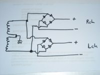
You mean two bridges sharing the same secondary ("parallel"), right?
If that is the case, you don't need other caps. The ringing frequency is determined by one of these caps plus the leakage inductance of the secondary, which don't depend on the bridges. The cap's value is large enough to ensure that this frequency will not actually depend on the capacitances introduced by bridge rectifiers - this dependence is made small, so it goes unnoticeable.
To cut the story short, changes in the ringing will be very subtle, so that you will probably need the same resistor to damp it, or a slightly different value. So you don't need a cap change, just find the optimum snubbing resistor using this method.
At least this is what I understand.")
By the way, why two different bridges? I was thinking about doing that, but I learned it can introduce problems. If you mind, describe you application a bit more.
If that is the case, you don't need other caps. The ringing frequency is determined by one of these caps plus the leakage inductance of the secondary, which don't depend on the bridges. The cap's value is large enough to ensure that this frequency will not actually depend on the capacitances introduced by bridge rectifiers - this dependence is made small, so it goes unnoticeable.
To cut the story short, changes in the ringing will be very subtle, so that you will probably need the same resistor to damp it, or a slightly different value. So you don't need a cap change, just find the optimum snubbing resistor using this method.
At least this is what I understand.
By the way, why two different bridges? I was thinking about doing that, but I learned it can introduce problems. If you mind, describe you application a bit more.
Will these channels share a common ground?
Bear in mind that these two supplies are not electrically isolated.
Read this thread for additional information:
http://www.diyaudio.com/forums/power-supplies/205949-single-transformer-multiple-bridges.html
Bear in mind that these two supplies are not electrically isolated.
Read this thread for additional information:
http://www.diyaudio.com/forums/power-supplies/205949-single-transformer-multiple-bridges.html
If the transformer is to drive 2 bridge rectifiers, would i use twice the values for C2/3, i.e. C2=22nF, C3=330nF ?
Please see the bottom row of Figure 13 in the Quasimodo design note.
You have a center tapped transformer and so you need two complete snubbers: (2 of Cx), (2 of Cs), (2 of Rs). The number of electronic components is six.
You can attach your bellringer test-jig to secondary "leg #1" as diagrammed in Fig.13, and select an optimum snubber. Then you can decide whether you want to assume that the optimum snubber for "leg #2" is near-identical to the optimum snubber for leg #1. (page 12, paragraph 3). If you are skeptical, if you do not feel comfortable making this assumption, you can attach your bellringer jig to secondary "leg #2" and find an optimum snubber for it. Perhaps the optimum leg #2 snubber will be extremely similar to the optimum for leg #1. Or perhaps it won't.
Perhaps it may not be the best idea to connect two bridge rectifiers to your CT transformer; I will let you decide that for yourself. But whether you use one bridge or two, you certainly do need two snubbers.
Last edited:
I have tried and rejected dual rectified supplies off a centre tapped transformer.
The two amplifier channels buzz because they MUST share the centre tap and the pulsing currents running through that centre tap.
4 secondaries using quad bridges gives a buzz free two channel arrangement.
The two amplifier channels buzz because they MUST share the centre tap and the pulsing currents running through that centre tap.
4 secondaries using quad bridges gives a buzz free two channel arrangement.
Perhaps it may not be the best idea to connect two bridge rectifiers to your CT transformer; I will let you decide that for yourself. But whether you use one bridge or two, you certainly do need two snubbers.
ok, one snubber for each winding.
But regarding the value of cx/cs, due i stick with 10n/150n or double up to 22n/330n if i use two bridges?
You're right, running two amps off a single power supply is asking for trouble with the ground system. There is no single optimal point to ground it, like with a single amp..
Currently my preamp uses four bridge rectifiers off one CT transformer, no issues to report.
My power amp uses two bridge rectifiers off one CT transformer, here there is a 3-4mVp-p noise spike at the amps o/p, and it can just be heard over the amps residual noise with your ear right up to the speaker.
I like the idea of "separate" supplys to each channel for the power amp, or elements of the preamp ie phono stage/gain stage/active xover.
Ctrlx, do you have the power transformer in your possession, the one that you'll use in your final, end-use, project build? Have you built and debugged a Quasimodo test-jig yet? I don't see your userID on the list of people who purchased one of my leftover PCBoards, so I guess you'll construct it on a Vero board or even a solderless breadboard as shown in post #18 of this thread.
The first thing to do is to complete the longest lead-time activities: obtain the transformer, and construct the bellringer jig. Then you can start planning which R&C component values to use "at least as a starting point for further experimentation." (QM design note p.7).
The first thing to do is to complete the longest lead-time activities: obtain the transformer, and construct the bellringer jig. Then you can start planning which R&C component values to use "at least as a starting point for further experimentation." (QM design note p.7).
If you want to replicate the Quasimodo idea, the testbench audio amp will be the piece which provides an ultra low output impedance. The signal generator produces an 0.5V peak-to-peak square wave @ 120Hz, that you feed into the testbench audio amp. The audio amp has a voltage gain of ~ 20X, so the amp's output drives the injection capacitor Cx with a 10V peak-to-peak square wave. Cx drives (C3 + Rs) and the transformer secondary, replicating the Quasimodo topology. Just make sure the power amp has sufficient bandwidth to give < 30 nanosecond rise time (in this case: fall time!) on the square wave's edges.
Thats what i did, using the last setup of Fig 13 labeled centre tap secondaries.
As shown there the transformer is driving one rectifier, but i am driving two recitifiers (see post 64), hence my question regarding the cap values.
Ctrlx, one way to analyze the situation when you double the number of rectifiers (thereby doubling the rectifier capacitance contribution to Ctotal), is to consider this a variation in rectifier capacitance. A +100% variation in Crectifier.
If, before doubling, you had chosen Cx to be much much greater than (Ctransformer + Crectifier), so that your Ctotal was insensitive to variations in Crectifier and/or Ctransformer (reason #2 to use a CRC snubber), then a doubling of Crectifier does not change Ctotal = (Cx + Ctransformer + Crectifier) significantly. Thus the resonant frequency omega_n does not change significantly, and the optimum snubber resistance does not change significantly.
Another design approach might be, to estimate the capacitance of the second set of rectifiers (conservatively over-estimate), and increase Cx by this amount.
A third approach might be, to arbitrarily increase Cx by 46.2%. Or to arbitrarily increase Cx by P% for some value of P that you happen to like best.
Whichever snubber component values you select, you will still (A) build a snubber with those component values; (B) apply a bellringer test to your transformer with that exact snubber, and (C) dial in the optimum Rsnub (zeta = 1.0) for your particular transformer and for that particular choice of snubber capacitances. As long as your snubber gives critical damping with your transformer, it is optimum. Whether you have increased Cx, left Cx unchanged, or decreased Cx.
chosen Cx to be much much greater than (Ctransformer + Crectifier), so that your Ctotal was insensitive to variations in Crectifier and/or Ctransformer (reason #2 to use a CRC snubber), then a doubling of Crectifier does not change Ctotal = (Cx + Ctransformer + Crectifier) significantly. Thus the resonant frequency omega_n does not change significantly, and the optimum snubber resistance does not change significantly.
ok, i will go with 15nF (since i have stock) and 220nF.
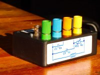
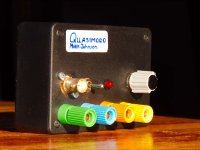
A few quick pictures of my 'final' implementation of the Quasimodo device
FdW: Lovely build, congratulations!
Your arrangement of binding posts is very clever; it lets you swap in whatever values of Cx and Cs you wish. It also lets you measure the resistance of potentiometer RV1. Finally it gives you the option to install a fixed resistor in parallel with RV1 if you so choose, to reduce the ohms-per-degree-of-shaft-rotation sensitivity. You know, to get those 3rd and 4th digits of precision
Would you please say what the BNC connector is for? Is it sync-out to the oscilloscope? Is it DC-power-in? Or is there a battery inside the enclosure?
Excellent job, thanks for showing us!
MarkJ
Would you please say what the BNC connector is for? Is it sync-out to the oscilloscope? Is it DC-power-in? Or is there a battery inside the enclosure?
It's the scope, 2x 9V inside
Anyone interested in a group buy of the V4 through-hole version? I have no experience in ordering PCBs and I'm a newbie to electronics and so I'm unlikely to be the right person to coordinate a buy but I would surely like to participate in one (even if the organiser earnt a return for their hassle).
- Home
- Amplifiers
- Power Supplies
- Simple, no-math transformer snubber using Quasimodo test-jig