I don't really know if this belongs in the tube section or not (seeming as all HV threads pretty much end up there), but here it goes.
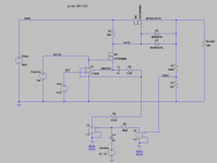
I've been fiddling around with a voltage regulator of my own design, which also happens to be an extremely common topology - I believe a similar circuit was shown in "The Art of Electronics" by Horowitz and Hill. It's a typical linear regulator circuit, except the caveat is that it obviously need to regulate HV (or about <400V in my case).
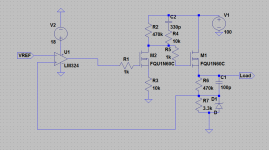
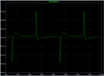
I've attached a schematic of my current prototype (with no current limiter) and it seems to regulate constant loads fine. However the transient performance is somewhat... lacking. Regulating the voltage down to about 50 volts (from only 100 to avoid burning out my poor IPAK package mosfets) and running into a pulsed load of 200 ohms, I got undershoot/overshoot spikes of a couple volts with very little ringing. I should mention that the current waveform across the load resistor has a rise time of about 1.2uS (I realize this is somewhat fast for this type of testing). I'd assume lower rise times into your load would result in a dramatically reduced spike - only problem is, I haven't figured out how to make a test rig to do this yet!
I'm a relative novice (well, pretty much totally new) at anything to do with control systems or feedback loops, so I'm a little puzzled at how you analytically analyze such a system and optimize it for transient response in whatever respect you want. How on earth do you go about analyzing a circuit like this for it's poles and zeros? I found I pretty much just added random capacitors to the circuit in order to get what I would consider the best looking transient response possible. Note that whatever I tried, I couldn't get the initial spike of the undershoot/overshoot under a certain value (though I could get the settling time and ringing to be practically non existent).
The LM324 is a relatively low bandwidth op-amp, so I was wondering if that had anything to do with my observations? Would replacing it with a higher bandwidth op-amp improve the response or does it simply not matter? How would I know what's causing that spike even if I inferred a bode plot from the loop gain?
I have a lot of questions and not much experience If anyone has experience in this type of thing, it would be much appreciated.
I've been fiddling around with a voltage regulator of my own design, which also happens to be an extremely common topology - I believe a similar circuit was shown in "The Art of Electronics" by Horowitz and Hill. It's a typical linear regulator circuit, except the caveat is that it obviously need to regulate HV (or about <400V in my case).
I've attached a schematic of my current prototype (with no current limiter) and it seems to regulate constant loads fine. However the transient performance is somewhat... lacking. Regulating the voltage down to about 50 volts (from only 100 to avoid burning out my poor IPAK package mosfets) and running into a pulsed load of 200 ohms, I got undershoot/overshoot spikes of a couple volts with very little ringing. I should mention that the current waveform across the load resistor has a rise time of about 1.2uS (I realize this is somewhat fast for this type of testing). I'd assume lower rise times into your load would result in a dramatically reduced spike - only problem is, I haven't figured out how to make a test rig to do this yet!
I'm a relative novice (well, pretty much totally new) at anything to do with control systems or feedback loops, so I'm a little puzzled at how you analytically analyze such a system and optimize it for transient response in whatever respect you want. How on earth do you go about analyzing a circuit like this for it's poles and zeros? I found I pretty much just added random capacitors to the circuit in order to get what I would consider the best looking transient response possible. Note that whatever I tried, I couldn't get the initial spike of the undershoot/overshoot under a certain value (though I could get the settling time and ringing to be practically non existent).
The LM324 is a relatively low bandwidth op-amp, so I was wondering if that had anything to do with my observations? Would replacing it with a higher bandwidth op-amp improve the response or does it simply not matter? How would I know what's causing that spike even if I inferred a bode plot from the loop gain?
I have a lot of questions and not much experience
If anyone has experience in this type of thing, it would be much appreciated.Attachments
Actually you are doing well not to have made an oscillator. The LM324 is not only slow, it is being used open loop and C1 is acting to increase the loop feedback speed while the 1K gate resistors are acting to reduce the phase margin. Try using a faster amp such as an opa37, check the corner frequency of the filters the 1K resistors gate resistors make with the gate capacitance. put some negative feedback on the op amp to reduce its gain to say 100. Place a low pass filter in the feedback to retain adequate phase margin through the op amp and regulator. To slow down the the load test, put a capacitor across the regulator output. It might be an idea to decide what loop response time is required.
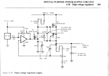
I think your circuit may have been inspired by Figure 6.47 in Horowitz and Hill, see below. But theirs includes numerous components that you omitted, which might be important. I'm especially worried about the lack of the resistor and capacitor at the inverting input of the opamp.
Attachments

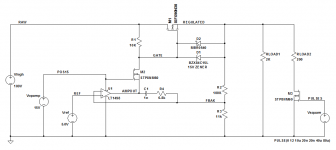
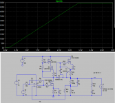
I had the same thought. So, just for the hell of it, I slapped together a quick-and-dirty simulation schematic (attached) and got some results (also attached).In addition, driving the first MOS from its source would be sensible: it would remove some of the phase shifts
A 10MHz opamp (LT1498) drives the source of M2, and the +15V power supply is applied to its gate; this keeps VGS below datasheet max limits. Zener D1 and Schottky D2 protect M1 against large VGS excursions.
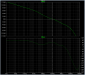
I interpreted "pulsed load of 200 ohms" to mean something like RLOAD1, RLOAD2, M3, and the pulse generator at far right. Transient simulation & AC simulation (Bode plot) are attached.
Also attached is the schematic for AC simulation; it breaks the feedback loop between R2-R3 and the opamp, then injects an AC stimulus. R5-C4 form a lowpass filter that opens the loop at all frequencies above DC. R4 mimics the Thevenin equivalent resistance of the R2,R3 voltage divider.
I'm not a tube guy or a high voltage guy; this was just a quick 45 minutes' hack on a lazy Saturday morning and IT MIGHT BE WRONG or dangerous. No warranty is expressed or implied. Use at your own risk. No technical support or moral support is offered now and none will be supplied later.
Attachments
I used the Horowitz and Hill supply for my tube tracer article in AudioXpress -- remember that it's really an amplifier -- a DAC was used to drive the opamp input and the output tracked very closely (if you weren't in a real hurry). here's a version with some of the demons caged:
An externally hosted image should be here but it was not working when we last tested it.
Oops. I dunno why I left the op-amp open loop I'd assume the thing wasn't oscillating simply because of all the stray parasitics as well as the huge drain capacitor on M2 fortuitously co-operating with the speed up capacitor. Assuming I rip out the capacitors I already have and actually start analyzing this circuit smartly, I'd think the main pole would be contributed by the miller effect at the gate of M2? Would it then be a good idea to minimize/eliminate the value of the gate stopper, or should it be used to help compensate the circuit later? Simulation seems to indicate that lower grid stoppers are better for transient response (I'm assuming this is because of the gate capacitance - meaning high RC constants for high value gate stoppers).
In the Horowitz and Hill circuit, they have a low pass filter across the op amp, which provides a modest positive phase boost. Am I right in thinking that this counteracts the pole provided by the miller effect and other poles at high frequencies? I believe I also read somewhere that value of the R in the RC of the op-amp loop should be chosen so the gain is less than unity at extremely high frequencies. Is this necessarily an issue?
I've studied a couple of control systems oriented units at university (I'm still a student), but nothing in reference to an actual working circuit (literally everything was done in transfer functions), hence why I'm unsure about a lot of this stuff. Are there any resources that you guys would recommend to wrap my head around feedback circuits?
This was only really a prototype built from parts lying around as a sort of learning exercise - I've attached the aforementioned low pass filter (the transient response didn't change one bit - guess it must have been pretty stable somehow!), and am now controlling it via a DAC and buffer. It actually regulates pretty well for my purposes, which is just a pre-amp supply for a single 12AX7/12AU7 tube in a guitar amp.
I'd assume the thing wasn't oscillating simply because of all the stray parasitics as well as the huge drain capacitor on M2 fortuitously co-operating with the speed up capacitor. Assuming I rip out the capacitors I already have and actually start analyzing this circuit smartly, I'd think the main pole would be contributed by the miller effect at the gate of M2? Would it then be a good idea to minimize/eliminate the value of the gate stopper, or should it be used to help compensate the circuit later? Simulation seems to indicate that lower grid stoppers are better for transient response (I'm assuming this is because of the gate capacitance - meaning high RC constants for high value gate stoppers).In the Horowitz and Hill circuit, they have a low pass filter across the op amp, which provides a modest positive phase boost. Am I right in thinking that this counteracts the pole provided by the miller effect and other poles at high frequencies? I believe I also read somewhere that value of the R in the RC of the op-amp loop should be chosen so the gain is less than unity at extremely high frequencies. Is this necessarily an issue?
I've studied a couple of control systems oriented units at university (I'm still a student), but nothing in reference to an actual working circuit (literally everything was done in transfer functions), hence why I'm unsure about a lot of this stuff. Are there any resources that you guys would recommend to wrap my head around feedback circuits?
This was only really a prototype built from parts lying around as a sort of learning exercise - I've attached the aforementioned low pass filter (the transient response didn't change one bit - guess it must have been pretty stable somehow!), and am now controlling it via a DAC and buffer. It actually regulates pretty well for my purposes, which is just a pre-amp supply for a single 12AX7/12AU7 tube in a guitar amp.
There are several poles in the system, the dominant one as far as I can tell is the network around the gate of M1 (look at R2), there is also a local feedback loop around this gate, C2R4R5 and the gate capacitance set the frequency response of this.
Then there is the OP amp driving M2, I would not eliminate R1, many OP amps do not like driving a capacitive load, It could be lower.
You are right the low pass filter, it is to slow the loop response down so that system never gets to a point where the other poles become a problem.
I forgot how to do Laplace transforms years ago so I wont be much help with control theory. As for Analogue design, Sedra and Smith is a good book.
- Status
- This old topic is closed. If you want to reopen this topic, contact a moderator using the "Report Post" button.
- Home
- Amplifiers
- Power Supplies
- HV Linear Supply Design - Loop compensation advice needed!