Hi,
I'm looking at this schematic to power a PSE 300b monoblock.
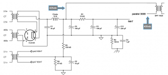
As I read it, the B+ line feeding the cap & choke is the 5v fillament supply's center tab.
In most schematic I see, there's no CT on the 5v winding, and the B+ into the choke comes from pin8 on the rectifier.
Is this any different, or am I just not reading it right?
Any explanation is greatly appreciated.
I'm looking at this schematic to power a PSE 300b monoblock.
As I read it, the B+ line feeding the cap & choke is the 5v fillament supply's center tab.
In most schematic I see, there's no CT on the 5v winding, and the B+ into the choke comes from pin8 on the rectifier.
Is this any different, or am I just not reading it right?
Any explanation is greatly appreciated.
An externally hosted image should be here but it was not working when we last tested it.
He,
As i see it there is no significant difference. The DC resistance of that winding will be virtually 0 or close to it.
Maybe it has something to do with convenient layout in the amplifier itself or it was done as a sort of RF decoupling.
anyway either one of the two options (directly to pin 8 or centre tapped) will work fine.
..
..
Another thing just popped into my mind -- is this case you will not favor one side of the filament. if you keep in mind that the filament is just a resistor if you tap it from pin 8 and the shortest way for the electrons to leave the filament is near the other side then this way of wiring it may help to balance cathode load.
PLEASE CORRECT ME IF I AM WRONG
Grtz Pim
Is the 5U4 a directly heated rectifier with a filament, or an indirectly heated rectifier with one side of the heater connected to the cathode? Octal rectifiers appear in both forms, and are roughly pin compatible. A centre-tapped filament winding would slightly favour the former, but would be a slight disadvantage for the latter. In either case not really worth worrying about unless the rectified voltage is lower than average, in which case the 2.5V extra AC might increase 50/60Hz hum.
NOTE - the "center tap" approach is WRONG in this instance. If the cathode is indirectly heated (which the diagram imputes), then using a center-tap of the 5 volt heater supply will actually ADD 2.5 volts of A/C hum to the rectified high voltage. Clearly, not optimal.
Ignore the center-tap, and derive HV from pin 8.
(And put in a 1H + 10uF capacitor in front of the 10H+30uF combo above... which will markedly reduce both residual hum and high frequency noise. And its cheap.)
Ignore the center-tap, and derive HV from pin 8.
(And put in a 1H + 10uF capacitor in front of the 10H+30uF combo above... which will markedly reduce both residual hum and high frequency noise. And its cheap.)
Yes, the5U4 is directly heated.
Thanks, I think I get it now. It basically doesn't matter if you draw the b+ from the CT or from pin 8 right? Except for the added 2.5v hum.
When drawing from pin8, the ct goes unused?
Also, the 30uf cap is non-polar? Is there formula for calculating the voltage after the cap, just before the choke?
Let's say I put in 400v, the 5u4 drops 50v so the rectifier puts out 350v? But after the cap it will'll be higher again?
Last edited:
I just looked up the 5U4 GT ... as you say, it is a DIRECT HEATER type tube, without a separate cathode. The circuit diagram is misleading (above).
In the case of DIRECT heated, then using the center-tap of the heater supply is the best method to reduce hum. Do not change the design.
There are virtually no 30 uF capacitors that are non-polar at 200-500 volts. 99.9% of them are high-voltage electrolytics. Therefore, they're polar. Get the poles right! Remember on the "choke side" is the positive voltage.
Also... remember that there is a WIRE connecting transformer(s) to rectifier(s) to capacitor, to choke. Ideally (some would argue), the capacitor's value and job is to capture and retain the PEAK value of A/C from secondary of transformer. This is 1.414 times the RMS output voltage.
Example. Secondary is 300 VAC. Peak is 1.414 * 300 = 425 volts. With the usual tube-rectifier losses, you will likely measure a RMS voltage (DC + imposed A/C component) on the positive capacitor lead of ... about 420 volts, or a 5 volt drop.
There are opposing forces at work in the design of the rectifier section of the power supply: to put as MUCH capacitance as is reasonable at every stage - to dampen ripple noise as much as possible - and to put as LITTLE capacitance near the front (closest to rectifier) to minimize the peak charging current audio-frequency noise (which tends to propagate through the chassis!)
One now-rare, but really decent solution to the charging noise versus oversized capacitor issue is this: a medium-high wattage resistor (10 watts) running at about 5 watts average (allowing for heavier-than-quiescent use), between transformer and rectifier plates. The resistors substantially limit the current flow, which in turn substantially lowers the peakiness of front-line (first) capacitor charging. Extends life of the rectifier tubes too. If 250 ma (say) is the design point for the high voltage supply, then for calculation, 125 ma per rectifier section is a good spot to start. P = R * I^2 (resistance times current squared), so 5 = R x (0.125^2) = R * .015625 ... R = 320 ohms. Voltage drop is 40 (nominally) volts.
The "40 volts" can also be gotten rid of with an inductor (and a reverse EMF bypass diode!) on each leg ... which effectively drops the voltage drop by a factor of 10, 20 or more. But in my older designs, it was just easier to get a higher voltage power transformer, and count on the voltage drop.
Design is a compromise between the unattainable and the incomprehensible.
GoatGuy
Thanks so much for the extensive reply.
Forgive me though but I'm struggling to understand how they get the required voltage for the 300b's. On the page they use a 400-0-400 transformer. Peak voltage would then be 1.414 * 400 = 565v so even with the 50v rectifier drop, it would be way to high with a 300b wanting about 400v?
Do you mean the CT in the schematic above or a wire not shown in that schematic?Also... remember that there is a WIRE connecting transformer(s) to rectifier(s) to capacitor, to choke.
Forgive me though but I'm struggling to understand how they get the required voltage for the 300b's. On the page they use a 400-0-400 transformer. Peak voltage would then be 1.414 * 400 = 565v so even with the 50v rectifier drop, it would be way to high with a 300b wanting about 400v?
400, 500 volts... 300B tubes stand up to it, safely. 1000? No. Is there any regulation of the power? Series or shunt, or both? It doesn't look like it from the diagram.
Without the series-between-powertransformer-and-rectifier resistors, the voltage would indeed be near 550 volts, provided your house power is "120" and the primary is also "120" wound. Mismatches there, as expected, have multiplicative effects on the secondary voltages.
It is also possible (indeed - probable) that the original specifications you're working from are IN ERROR. Happens all the time. Nothing new. I prefer to have the design-point of output tubes be within 20% of their "safe maximum ratings", to account for mismatches between line-voltage and power-transformer primaries. And, if there are "settings" on the primary (often a number of taps like "110, 115, 120, 125", I choose 120.
If you are in Europe, then "208, 210, 220, 230, 240, 277" are likely. Choose 240, generally.
The 300B family of tubes has a variety of maximum voltage ratings dependent on the manufacturer's specs. With small amounts of anti-corona engineering (folded-back plate edges, for instance), maximum voltages can easily be extended to 700+ to 1000 volts. The more important problem is that the 300B plate is only rated for 40 watts of dissipation. And in the end, if the manufacturer adds head-dissipation fins, anti-corona engineering, special coatings to grids and plate surfaces, ... then is it still a 300B?
GoatGuy
I've been drawing up this according to their specs as an more complete version of the schematic in the OP. Reading your comments, this is just incorrect? In reality, the voltages indicated would be much higher?
I like to believe the numbers work out, them being a well known company and all but I don't get it ...
I like to believe the numbers work out, them being a well known company and all but I don't get it ...
Attachments
Look up 5U4 GB ... page 2 of data sheets. specifies that there will be a 55v drop at 275 ma. So... 400 * 1.4 = 560, minus "60" (close to 55) = 500 volts. Still over the 450V "max recommended" operation point of 300B. I'd use 330 volt windings instead. (330*1.414)-60 = 406 volts DC. After your choke... probably 400V. Clearly within the 300B's envelope.
Also, what's up with all those transformers?
If your using a graphics package like Illustrator for this ... then at least label the primaries as your primary - 120 or 240 VAC ... for whatever country you're building for (or... hint, hint... a multitap/multi-wound primary that allows configuration for either 120 or 240 standards!) ... Its the secondaries that have the lower/higher voltages.
Anyway, have fun... Its all fun ... until someone gets hurt!
GoatGuy
It looks like separate transformer because of the app i'm using (circuitlab.com), in reality it's 1 transformer.Also, what's up with all those transformers?
I've been playing a bit with PSUD and the numbers do seem to work out. It depends heavily on the load that is on the circuit after the rectifier.
With an input of 400VAC and a load of around 1K, the voltage after the choke is around 420v RMS.
With a 5k load, it's 520v RMS and with 500R it's 380v RMS. So if the load is right, the voltage should be too.
- Status
- This old topic is closed. If you want to reopen this topic, contact a moderator using the "Report Post" button.
- Home
- Amplifiers
- Power Supplies
- Help me understand this schematic