Here are some bode plots of a Fairchild LM317 under various conditions:
An externally hosted image should be here but it was not working when we last tested it.
An externally hosted image should be here but it was not working when we last tested it.
An externally hosted image should be here but it was not working when we last tested it.
An externally hosted image should be here but it was not working when we last tested it.
An externally hosted image should be here but it was not working when we last tested it.
Bode plots are the real (curvy) thing. The straight line approximations are very useful as they are usually good enough to spot problems.
No, they are straight lines !
Bode plot - Wikipedia, the free encyclopedia
They represent straight approximation of a function, not the function itself. Sometimes, the asymptotic straight line to the function.
Wikipedia disagrees. It says the Bode plot can be approximated by straight lines, not that the Bode plot is straight lines. The Bode plot is the full curvy plot, as I said.Wikipedia said:If the transfer function is a rational function with real poles and zeros, then the Bode plot can be approximated with straight lines. These asymptotic approximations are called straight line Bode plots or uncorrected Bode plots and are useful because they can be drawn by hand following a few simple rules.
Interesting. Can you tell or show the audience how your test setup looks like?
An externally hosted image should be here but it was not working when we last tested it.
Schematic -- nothing exceptional or creative
An externally hosted image should be here but it was not working when we last tested it.
it does not look exceptional.
What is does show is that much thought needs to be implemented to get good test jigs. Then these good test jigs can reveal lots that we do not yet know about our circuits.
eg. Hamon divider
I only recently discovered that this existed. It is so simple to implement and yet is capable of far greater accuracy than I can ever achieve by ANY other method. And that is not an exaggeration. I can get +-20ppm with a few hours work on a two stage Hamon Divider giving 1:10:100 ratios that I just cannot get otherwise.
Mr Hamon is brilliant.
Your schematic shows that you too can think and devise tests.
DIYAUDIO member Conrad has a Hamon divider tutorial on his site:
How to Build a Hamon Resistor Divider Network
The schematic of the bode tester isn't original to me.
How to Build a Hamon Resistor Divider Network
The schematic of the bode tester isn't original to me.
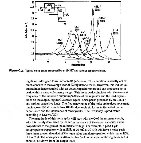
That's excellent stuff! IMO, the 317 is remarkably capable if used properly. There was an old paper/datasheet that showed the noise peaking if the output cap esr was too low. It's on line somewhere, though I can't locate it right now. No doubt it was part of your inspiration!
One thing the test setup here shows is how useful transformers can be, solving isolation and common mode problems that would otherwise be difficult.
One thing the test setup here shows is how useful transformers can be, solving isolation and common mode problems that would otherwise be difficult.
Could we extrapolate from that graph and guess that 47uF to 220uF may be even better at attenuating that noise peak?
Alternatively, would adding a low ohm resistor in series with the cap bring down the peak?
Which would be more effective?
100uF with the intrinsic esr of a standard commercial electrolytic, or a 22uF with 0r1 added to damp the peak.
What do you think?
Would Jack's test rig show this? I am trying to interpret the last pic in the series (47uF+1r0). What is it showing us?
- Status
- This old topic is closed. If you want to reopen this topic, contact a moderator using the "Report Post" button.
- Home
- Amplifiers
- Power Supplies
- Some LM317 Bode Plots
