Hi Frank, the non-inductive film caps where two separate opposite windings are in series (eg, Mundorf and Intertechnik Audyn caps) seem to be built like tanks and can handle high voltages. The 0.47 microF values are relatively affordable, but those 22 microF are quite pricey. Your right, those manufacturers do surely crow about their designs, and make you pay for it dearly!
Yikes, I looked at an older catalogue and some of the higher voltage units there from conventional manufacturers gave one sticker shock! So, I went on-line and looked at element14, used to be Farnell InOne, and was pleased to see Vishay and Epcos at reasonable prices: Vishay MKP1848S62010JY5F, 20uF, 1000V, about $AU11. So, there are units at sensible prices, and if you can drop the voltage requirements a bit you get more cap for your buck.
As regards temperature, I can't imagine you'll be placing these parts in the really hot positions, but if the worst comes to the worst, those units are rated up to 105deg C, operating, life of 100,000 hrs at 70deg C.
So, I reckon those parts should do it, to try out, from Vishay, etc -- forget the fancy stuff!
Frank
Thank you! That is exactly what I was looking for. I always to have trouble getting the correct filter settings to narrow down what I'm looking for. Does the same capacitor come in 0.47 microF? Or should I get ceramics for both 0.47 and 0.01 microF? I tried searching that site, but I get so many listings, I don't know which to choose.
I agree about these suppliers, they seem to keep fiddling with their websites, just when you get a handle on how to get around nicely, they up and change everything again, help!!
On the webpage I posted for that cap there was a link to the technical data sheet, a PDF, and that showed minimum value was 1uF. So no joy there. I altered the 'Select a Max' value for Capacitance to 0.5uF, and 'Select a Min' for Voltage Rating to 600V or so, and that showed me 2 reasonable units, Epcos B32674D8474K - EPCOS - CAPACITOR PP FILM, 0.47UF, 875V | element14 Australia, 850V, $3 and a Vishay BFC233814474 - VISHAY BC COMPONENTS - CAPACITOR PP FILM 0.47UF, 1KV | element14 Australia, 1000V, $5. Last step, changed Select Max for Cap to 10000pF, ie. 10nF or 0.01uF, and huge range of options, all film: Epcos B32652A103J - EPCOS - CAPACITOR PP FILM 0.01UF, 1KV | element14 Australia, and Evox Rifa PHE448RB5100JR06 - EVOX RIFA - CAPACITOR, 0.01UF, 1600V, 15MMP | element14 Australia, both less than $2. Here you could also consider ceramics, I was just looking at film, and over there it's a huge selection, mostly surface mount, but say try the Kemet C322C103JDR5CA - KEMET - CAPACITOR, 10NF, 1000V, X7R | element14 Australia for $3. I would recommend you straighten the leads if you get this, right angles or sharp corners are a no-no if you're trying to control HF energy.
Frank
Hi Frank, will this 0.01 microF ceramic cap work just as well? The leads are straight on these cap. Temperature rating is not high as the Kemet, though.
562R5GAS10 - VISHAY CERA-MITE - CAPACITOR, 10NF, 1000V, Z5U | element14 Australia
562R5GAS10 - VISHAY CERA-MITE - CAPACITOR, 10NF, 1000V, Z5U | element14 Australia
I wouldn't get too fussy about picking one versus another: that looks fine, the lead spacing in fact is a bit greater which may be the most important factor, if it reduces the length of wiring needed to get the component where it needs to be connected. The higher the frequency one's worrying about, which is what these small value caps are relevant to, the more important the precise physical orientation, shape and placing of things are, to get components to do what you want them to do!
Don't worry about how the leads come, a pair of needle point pliers can sort that out, don't be scared to bend them. And don't worry about neatness, making things look "nice" is a very low priority when you're trying to kill interference effects!
Frank
Don't worry about how the leads come, a pair of needle point pliers can sort that out, don't be scared to bend them. And don't worry about neatness, making things look "nice" is a very low priority when you're trying to kill interference effects!
Frank
Hi Frank, my main power supply caps are film caps (there are 12 of these 760 microF caps), no electrolytics in my amp. And these film caps have ESR of 1 mOhm measured at 10 kHz. The 20 microF bipass cap you referenced has 0.0095 Ohm, which is almost 10x higher than my main power supply caps:
http://au.element14.com/vishay/mkp1848s62010jy5f/capacitor-1000v-20uf-5/dp/2133988
Won't the bypass caps affect the performance of the power supply caps in bad way?
http://au.element14.com/vishay/mkp1848s62010jy5f/capacitor-1000v-20uf-5/dp/2133988
Won't the bypass caps affect the performance of the power supply caps in bad way?
Last edited:
Tsk, tsk, I've just seen your pursuing of advice on Audiogon also, you're really making sure you're getting a good cross-section of opinions!
But that's OK, it's worthwhile trying to achieve maximum understanding of a situation, though it would have been of value to have known from the beginning that the main caps were of the type you mention. They obviously are of very high quality and the number in parallel means that the 20 or 22uF unit is completely redundant, unnecessary, but the other 2 smaller units will still be of value, because of their very small size. In which case, the 50 times rule means that they're completely "safe" ...
There is some excellent advice in that Audiogon thread ...
Frank
Your advice is more clear to me and makes more sense. I thought I mentioned having film power supply caps early on, but my mistake sorry. However, I'm still wondering if the two small value bypass caps you recommend has higher ESR than my power supply caps. Even if they did, would it matter in this application?
Thanks for the thumbs up!
It's not the ESR that's at issue but the associated ESL, the parasitic inductance that is associated with the construction of the device that's the problem. The combination of that inductance with the rated capacitance of the device means there is a resonant frequency intrinsic to the cap, some spec's tell you what it is. And only at that special frequency does the extremely low ESR actually mean anything, on either side of this frequency the impedance seen by the circuit shoots up dramatically.
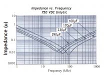
Now that I know the nature of what you're using, let's look at somewhat similar film caps made by ecicaps, a range called Unlytic:

Look at the curve corresponding to 650uF, pretty close to what you've got. Yes, it gets down to 0.005 ohms, but then it shoots up as the frequency increases, hits 0.3 ohms at 1000kHz, 1MHz; not so impressive now! This is because the ESL is dominating now. Those 10 caps in parallel mean that you have theoretically improved all the good stuff by 10 times, so at 1MHz the impedance is 0.03 ohms, BUT, long lengths of wiring are needed to connect all those caps together, because of the physical size of them, and hence most of the theoretical advantages, at higher frequencies, disappear!
Now consider a cap in the same range, 10 times smaller:

The 50uF curve here has a key characteristic, the minimum impedance, where the ESR has a chance to do its job, has moved to a much higher frequency, roughly 5 times greater, and still looks pretty good, about 0.007 ohms. Something that those 10 560uF caps would be struggling to do, see what's going on here? It's the combination of the rated capacitance, the ESR, and the ESL that tells you where a cap will do a good job of bypassing, in terms of frequency, which is why paralleling several of different values works for a frequency range ...
Frank
It's not the ESR that's at issue but the associated ESL, the parasitic inductance that is associated with the construction of the device that's the problem. The combination of that inductance with the rated capacitance of the device means there is a resonant frequency intrinsic to the cap, some spec's tell you what it is. And only at that special frequency does the extremely low ESR actually mean anything, on either side of this frequency the impedance seen by the circuit shoots up dramatically.
Now that I know the nature of what you're using, let's look at somewhat similar film caps made by ecicaps, a range called Unlytic:
Look at the curve corresponding to 650uF, pretty close to what you've got. Yes, it gets down to 0.005 ohms, but then it shoots up as the frequency increases, hits 0.3 ohms at 1000kHz, 1MHz; not so impressive now! This is because the ESL is dominating now. Those 10 caps in parallel mean that you have theoretically improved all the good stuff by 10 times, so at 1MHz the impedance is 0.03 ohms, BUT, long lengths of wiring are needed to connect all those caps together, because of the physical size of them, and hence most of the theoretical advantages, at higher frequencies, disappear!
Now consider a cap in the same range, 10 times smaller:
The 50uF curve here has a key characteristic, the minimum impedance, where the ESR has a chance to do its job, has moved to a much higher frequency, roughly 5 times greater, and still looks pretty good, about 0.007 ohms. Something that those 10 560uF caps would be struggling to do, see what's going on here? It's the combination of the rated capacitance, the ESR, and the ESL that tells you where a cap will do a good job of bypassing, in terms of frequency, which is why paralleling several of different values works for a frequency range ...
Frank
Attachments
Last edited:
No, but thank you for the compliment! ")
There are people on this forum with vastly more knowledge and experience than myself, I probably have a good knack for picking up information that is directly relevant to what I'm strongly interested in, understanding the subtle factors that contribute to good sound.
Cheers,
Frank
There are people on this forum with vastly more knowledge and experience than myself, I probably have a good knack for picking up information that is directly relevant to what I'm strongly interested in, understanding the subtle factors that contribute to good sound.
Done! SV09AC474KAR - AVX - CAPACITOR CERAMIC 0.47UF 1000V | element14 Australia, but a bit pricey, $22. A film cap should still do the job perfectly well, but if you want to experiment, go for it! Let us know how it goes, what sort of improvement, or otherwise, you get ...Now, only if 0.47 microF ceramic caps at 1kV could be found.
Cheers,
Frank
Thanks again Frank! Unfortunately, $22 is not considered pricey by "audiophile" standards. The high cost of "audiophile" components drives me nuts because I know most of it is just marketing BS.
BTW, you read the Audiogon thread where some recommended 1/100 ratio when selecting cap values for bypassing. Is this any better or worse than 1/50?
BTW, you read the Audiogon thread where some recommended 1/100 ratio when selecting cap values for bypassing. Is this any better or worse than 1/50?
No, once you get past the 50 to 1 ratio then there won't be any problems with resonance, which is why you need at least this gap. So, 100 to 1, 200 to 1, etc, are all fine. But, remembering back to the curve of the impedance with frequency, that classic V shape, if the gap is too large then there is insufficient overlap of the characteristics, the 2 together will look like a W, you're not getting the best result.
Again, don't get paranoid about it: anywhere in the area of 50/1 to 100/1 will be fine, you don't need to get the precise value to make the ratio just so, possibly will give you more options when buying!
Frank
Again, don't get paranoid about it: anywhere in the area of 50/1 to 100/1 will be fine, you don't need to get the precise value to make the ratio just so, possibly will give you more options when buying!
Frank
- Status
- This old topic is closed. If you want to reopen this topic, contact a moderator using the "Report Post" button.
- Home
- Amplifiers
- Power Supplies
- Mundorf M-Cap Supreme as bypass cap?