Reservoir Capacitance Requirements
I finally figured out how to calculate the worst-case minimum required reservoir capacitance for a sine signal at less than the fmains frequency, in the presence of rectifier charging pulses.
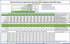
There's an interesting table of C values versus frequencies, for each de-rated max output power that could be chosen for a given theoretical max power, in the attached spreadsheet.
You can enter your Rload, Vrail, fmains, etc, and it calculates everything else for you. It basically shows what Rated Max Power you would have, for different capacitances, in order to avoid clipping when operating at the rated max output power.
It ALSO shows the lowest frequency sine your amplifier could reproduce without clipping, for a given reservoir capacitance, when operating at the rated max output power.
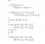
I also made an MS Word doc that gives the equations used in the spreadsheet, with partial derivations. (I didn't want to take the time to enter the many equations for all of the steps of the derivations.)
I finally figured out how to calculate the worst-case minimum required reservoir capacitance for a sine signal at less than the fmains frequency, in the presence of rectifier charging pulses.
There's an interesting table of C values versus frequencies, for each de-rated max output power that could be chosen for a given theoretical max power, in the attached spreadsheet.
You can enter your Rload, Vrail, fmains, etc, and it calculates everything else for you. It basically shows what Rated Max Power you would have, for different capacitances, in order to avoid clipping when operating at the rated max output power.
It ALSO shows the lowest frequency sine your amplifier could reproduce without clipping, for a given reservoir capacitance, when operating at the rated max output power.
I also made an MS Word doc that gives the equations used in the spreadsheet, with partial derivations. (I didn't want to take the time to enter the many equations for all of the steps of the derivations.)
Attachments
You the man Gotee......... Why can't all of this just be nice and easy..... If you have been reading the Blowtorch thread recently you will see some parallel research into the transformer side of things leaving out the capacitor and only looking at the actions of the tranny. It just keeps getting more complex when you look at each components interaction with the mains currents.
Steven
Steven
Easy generally means problems that can be resolved by applying well understood concepts. A power supply's pretty much a filter. The impedances and loading are rather different than what's found in things that are usually called filters, but a passive linear supplies we're focusing on here are integrators like any other lowpass filter. One major difference is mainstream filter theory, if you will, assumes a constant load impedance on the filter. This is a pretty good approximation for class A amplifiers, which is why class A loading usually feels like a major simplification in supply design. It's someplace between a poor to awful approximation for class B, D, etc. The other major difference is mainstream filter theory focuses on filters where either both the input and output are continuous time or they're both discrete time (sampled). The bridge diodes mean the supply "filter" essentially has a discrete time input and an continuous time output.
In other words, a power supply is a DAC. In particular, it's a DAC with, by conventional DAC standards, a very noisy and extremely low quality sample and hold circuit into the switched capacitor filter. So not only do you have to think outside the box with respect to filter theory most of the simplifying assumptions that can be made with DACs don't apply to power supplies. A full wave bridge yields a Nyquist rate equal to the mains frequency. This means nearly all of the bandwidth of interest is aliased, something which is studiously avoided in most discrete time systems.
Power supplies would be a lot less fun and challenging if they didn't make you think sideways like this, though. I was running an analysis similar to Tom's for a class AB active triamp I'm working on not too long ago, which throws in some extra twists as you've one channel's worth of audio signal that's split across three different loads to the supply. Since there are three channels rather than one or two there's higher quiescent dissipation and hence a little of the load shifts from class B to class A. If you decide not to ignore this life gets rather interesting since the crossover means all the slow moving portions of the load are assigned to whichever amp is driving the subwoofer. Therefore, the midrange channel pretty much operates above the bridge's switching rate and be treated as an RMS load rather than the almost DC cases which come up in the deep bass for the sub channel. The same applies to a tweeter channel, but its RMS level will be lower due to the mid and sub taking the lower frequencies. So you end up with parameter sweeps over crossover frequency and music power spectral densities as well as the usual mains level and capacitor size variations.
You the man Gotee......... Why can't all of this just be nice and easy..... If you have been reading the Blowtorch thread recently you will see some parallel research into the transformer side of things leaving out the capacitor and only looking at the actions of the tranny. It just keeps getting more complex when you look at each components interaction with the mains currents.
Steven
It looks like everyone who has ever tried to analyze a simple transformer-rectifier-capacitor power supply has found it to be "surprisingly complex", at least mathematically.
One reason I've been playing with this stuff is to try to make it easier for everyone else.
Also, I hope to dispel some myths and head off some common mistakes and misconceptions, so people might have an easier time, and a better chance at getting better results, sooner rather than later.
Just to recap a little:
One of the first important concepts that needs to be emphasized is that the CURRENT is where the action is. The current is the music signal, and is what the power supply is for, and what it needs to be best at providing. The usual "voltage centric" view of the power supply (and of everything else) misses the point and is less likely to lead to a good understanding of what is most important.
It would be nice to also hold the voltage constant but often it's not too critical. Note, too, that ripple voltage is not the periodic sawtooth from the textbooks, unless the load is extremely boring. Ripple voltage is caused by the music current, as it drains the caps between charging pulses from the rectifier, and also as it gets pulled through the rails' inductances (and resistances), since V = L di/dt (and V = iR).
Decoupling caps, like little power supplies right at the point of load, can help stop ripple from even starting, but are also necessary for accurate transient response and feedback operation, especially for the higher-frequency and shorter-duration events. Inductance is our enemy and distance/length means inductance. I would use at least 10 uF per Watt, within 13mm of power output devices.
Rated maximum Output Power and Clipping: Many people think that as long as the peaks of the output signal voltage stay below the troughs of the ripple voltage, clipping will be avoided. They also calculate the max rated power by assuming that the output voltage can peak just below the ripple's minima. Both are actually incorrect.
They forget that the amplifier has to occupy some of the available voltage range, between the rail and ground. Look at a schematic: Current goes from PSU rail to amplifier then to load then to ground. There is usually at least a transistor's Vce or Vds, and often a low-value resistor, between the power rail and the load.
There is a minimum voltage that must exist across the transistor, for it to operate (Vceo-something, maybe). Certain chipamp datasheets call the minimum voltage between the power and output pins the "clipping voltage", and have plots of it, versus the rail voltage. In my spreadsheet it is called Vclip. It's usually 2 to 5 volts.
It is almost identical to a linear regulator's "dropout voltage". If the signal voltage waveform reaches too high, while at the same time the ripple voltage's waveform sags too low, the ripple voltage will make incursions into the amplifier's "clipping voltage" space, which will effectively gouge chunks out of the output voltage waveform.
Anyway, none of that is "hard" to understand. But it's hard to accurately account for it all unless the actual calculations are performed. So that's one of the main purposes for sharing the spreadsheets I have developed. It would be very inefficient, from the universe's point of view at least, if everyone had to "re-invent the wheel" every time they wanted to make a decision about a power supply.
Last edited:
For all of the math lovers out there, I added the detailed derivation steps for the case where the intervals between charging pulses are less than one-half of the sine signal wavelength (i.e. sine frequencies less than AC mains frequency). I also used MS Word's equation editor to format most of the equations that were previously written with plain text.
If you don't have a compatible version of MS Word, a sample is attached as a jpg, so you can see what you're missing.
If you don't have a compatible version of MS Word, a sample is attached as a jpg, so you can see what you're missing.
Attachments
Thanks for the kind words.
I made a minor change, so that the top row can be changed, to make it easy to change the rated max power's percentage of the theoretical (zero-ripple) max power. And I added a few more columns.
Screen images and new version are attached. In the sample screen images, I tweaked the rated vs max power percentages so that the capacitance values came out to more-or-less standard cap values, or combinations of them. The only change I made between the two was to change the rail voltage from 32.7 Volts (for 50 Watts using 22000 uF) to 45 Volts (for 100 Watts using 22000 uF).
Attachments

Last edited:
small question ?
So about 200,000 uf is about he max amount to have an effect on power supply stiffness ?Thanks for the kind words.
I made a minor change, so that the top row can be changed, to make it easy to change the rated max power's percentage of the theoretical (zero-ripple) max power. And I added a few more columns.
Screen images and new version are attached. In the sample screen images, I tweaked the rated vs max power percentages so that the capacitance values came out to more-or-less standard cap values, or combinations of them. The only change I made between the two was to change the rail voltage from 32.7 Volts (for 50 Watts using 22000 uF) to 45 Volts (for 100 Watts using 22000 uF).
No.So about 200,000 uf is about he max amount to have an effect on power supply stiffness ?
The stiffness is relative to the load current.
A small low current amplifier will "need" less capacitance than a large high power amplifier, for the same apparent stiffness.
please forgive me for Stating a general rule of thumb kind of value for this range of amps when others are looking at exact values. The side effect of 100,000 uf and larger cap is the turn surge must be controlled but we all know that. I should have explained my previous statement better about the 200k uf amount . Gootee has done some very good work on showing the range of cap need to produce what level of power supply rigidity . Andrew T your point is well taken.No.
The stiffness is relative to the load current.
A small low current amplifier will "need" less capacitance than a large high power amplifier, for the same apparent stiffness.
"Vrail" is NOT the "unloaded" value.
For some reason I wrongly labeled the Vrail entry as the "unloaded" peak rail voltage. I apologize for any inconvenience.
The rail voltage should be entered for loaded conditions, for "Vrail".
i.e. From the unloaded rail voltage, one must subtract two diode drops, assuming the diodes are conducting the current that would result if the load had a constant DC voltage across it, with an amplitude equal to the peak voltage of a sine at the maximum rated output power. (i.e. Output power = 1.414x the rated maximum output power.)
If in doubt, just use the largest diode drops that are spec'd for the maximum forward current of the diodes to be used.
For silicon diodes, it would probably be safe to subtract 2 to 2.2 Volts from the transformer secondary's peak output voltage. For Schottky diodes, it would probably be safe to subtract 0.9 to 1.0 Volt.
please forgive me for Stating a general rule of thumb kind of value for this range of amps when others are looking at exact values. The side effect of 100,000 uf and larger cap is the turn surge must be controlled but we all know that. I should have explained my previous statement better about the 200k uf amount . Gootee has done some very good work on showing the range of cap need to produce what level of power supply rigidity . Andrew T your point is well taken.
No problem. Note that in the latest version of the spreadsheet, you can just increase the percentages in the blue row, near the top, to see larger capacitances. For example, enter 99.9 percent, or 99.99 percent. That makes the PSU try to leave almost no room for any ripple, which makes the needed capacitance value "excessive". You might even have to widen the columns, to see the resulting numbers. (If a number is too long to fit within the column width, it might display as ######## instead of the number. In that case, just go to the very top, where the column letters are, and hover over the line between two columns. When the cursor changes, you can left-drag to widen the column to the left of the cursor.)
Last edited:
Your spreadsheet seems to assume the mains are a pure sine with really low source impedance. They are remarkably low Z with in reality as much as 500A peak available but rarely less than 3% distortion, mostly flattening of the peaks. (From all the other rectified loads on the power lines.) This means two things, first that the peak voltage available will be different from what is calculated from an RMS (or average) meter, and second, not knowing the conduction angle or the real peak current makes it harder to calculate the voltage drops in the diodes, transformer, and wiring. Perhaps you can show what the peak current on the AC side of the supply would be?
Larger caps may be stiffer but with the short conduction angle and higher currents the net voltage on the supply is less, leaving less power available. In reality the difference between 200,000 uF and 40,000uF could be less than a less than a dB of maximum output and the supply and components may last a lot (10X) longer if the caps are smaller. In the '80s there was a fad for huge cap arrays for amplifiers. The real fallout was burned connectors on the power connections and overheated diode arrays. Not to mention the increased EM field from upping the peak current from 10A to 100A.
Of course I will be using it since its very good, well documented work.
Thanks, Demian.
I think that everything you said is correct.
I am still just a dabbler in this area. So there may be major omissions and mistakes in anything I have posted. But I have consistently recommended using LT-Spice or some other more-robust method of modeling and simulation.
The spreadsheets I have posted were intended mainly for use by those who are unwilling or unable to invest the effort and time required to make the jump to spice.
Assuming you were referring to the psu simulation spreadsheet that produces a plot of the psu output voltage (et al), you might be able to add resistance and inductance via the two fields for that, which essentially add them in series with the secondary winding.
There are other significant omissions, as well, such as no parasitic inductances except that of the transformer, and no accounting for amplifier inefficiency. On the other hand, the VBA code is accessible.
I finally figured out how to calculate the worst-case minimum required reservoir capacitance for a sine signal at less than the fmains frequency, in the presence of rectifier charging pulses.
There's an interesting table of C values versus frequencies, for each de-rated max output power that could be chosen for a given theoretical max power, in the attached spreadsheet.
You can enter your Rload, Vrail, fmains, etc, and it calculates everything else for you. It basically shows what Rated Max Power you would have, for different capacitances, in order to avoid clipping when operating at the rated max output power.
It ALSO shows the lowest frequency sine your amplifier could reproduce without clipping, for a given reservoir capacitance, when operating at the rated max output power.
I also made an MS Word doc that gives the equations used in the spreadsheet, with partial derivations. (I didn't want to take the time to enter the many equations for all of the steps of the derivations.)
All,
The minimum capacitances in the SINE portion of the spreadsheets I posted in posts 1821 and 1828 are a little less accurate than they could be. Currently, they are pretty close, assuming that ESR is very small (which it probably always will be). But even though the results are very close to correct, part of the math was not done correctly so I feel the need to revise it. I will upload a new set of xlsx and docx files, tonight or tomorrow.
Cheers,
Tom
gootee,
You actual use of math was nice and refreshing.
Of course there are many other issues (including the effects of an almost constant current load on the power supply capacitors) that are of some importance.
If you really want to spend too much time on this then try looking at transformers!")
Gold star for the nice work.
ES
P.S. In normal sized power supplies with transformer regulation into a full wave bridge conduction angle is almost 60 degrees!
You actual use of math was nice and refreshing.
Of course there are many other issues (including the effects of an almost constant current load on the power supply capacitors) that are of some importance.
If you really want to spend too much time on this then try looking at transformers!
Gold star for the nice work.
ES
P.S. In normal sized power supplies with transformer regulation into a full wave bridge conduction angle is almost 60 degrees!
I'm a lazy fella, my poor old head would explode trying to follow Tom's maths, so I take the easy way out and use LTspice. It's important that all the realities of an actual circuit are taken into account, including dodgy mains quality, right through to loads comparable to actual speakers -- something I've explored for quite a while -- and it is very revealing as to what's important.
I hope at some stage to do a full analysis of this sort of thing, in sim's, when my energy reserves are topped up a bit ...
Frank
I hope at some stage to do a full analysis of this sort of thing, in sim's, when my energy reserves are topped up a bit ...
Frank
Hello !
I wonder how many Joules are stored in power supply caps of an average solid state amp and of an average tube amp.
I have the feeling that there are many more Joules in the case of the tube amp.
Could this lead to something ?
Thanks for the very interesting 3D
Regards,
gino
I wonder how many Joules are stored in power supply caps of an average solid state amp and of an average tube amp.
I have the feeling that there are many more Joules in the case of the tube amp.
Could this lead to something ?
Thanks for the very interesting 3D
Regards,
gino
Last edited:
This seems unusually high....................
P.S. In normal sized power supplies with transformer regulation into a full wave bridge conduction angle is almost 60 degrees!
The pics I have seen all support a MUCH shorter conduction period.
Even the saw tooth ripple on the smoothing caps shows a MUCH shorter conduction period.
- Status
- This old topic is closed. If you want to reopen this topic, contact a moderator using the "Report Post" button.
- Home
- Amplifiers
- Power Supplies
- Power Supply Resevoir Size