As I said in post 5, it eventually comes round to a ripple calculation. The worst case is low frequency square wave signals, where you have to design for Ipk (=2Idc) and the caps have to maintain sufficient voltage to provide the required output voltage for the 10ms (or 8.33ms) between charging pulses. In real life it is slightly less than 10ms because the charging pulse is not infinitely narrow.Terry Given said:So in otherwords we can probably just do the standard 50/60Hz ripple design, but use 2*Pout instead of Pout.
How much voltage droop can you afford? That depends on the minimum voltage drop across the output stage, and how much the supply voltage exceeds the minimum needed for the output spec. This in turn means that there is no magic answer in the form of J per W.
The other issue is PSRR, which may or may not impose a stronger limit. However, PSRR can be designed away so should not be a problem.
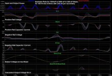
I agree, Andrew, that first cut I did is not presenting the right information, mainly because the transformer was being driven by too high a voltage in the sim. So I redid it, using RMS everywhere, and making the load axis logarithmic. Now, the bright vertical marks the rated load situation, 24.8V out, 4.8A, 7.2% regulation. A lot closer to a realistic device, I believe ...Am I reading the plots correctly?
At infinite load resistance: Vout = 73.7Vpk
At 10r load resistance: Vout = 71.2Vpk
At 10r load resistance: Iout = 7.12Apk
VA @ 10r loading = 253
regulation @ 253VA = 3.5%
This would seem to indicate that the transformer model is probably equivalent to a toroid that is quite a bit larger than 253VA, 25.1+25.1Vac
This actual toroid would normally have a 5% to 7% regulation.

Frank
119VA for a 24.8Vac
7.2% regulation seems about right for a toroid and very low for an EI.
So I suppose this is typical for a transformer powering a single channel 100W amplifier.
Is that VA rating for one secondary winding? Or have you paralleled two secondaries to get the total VA for a dual secondary 24.8+24.8Vac transformer?
Can you confirm that this is the transformer being used in the other simulations, particularly by Gootee. Or are they using something different? Like 6 off in parallel !
This should give about 36.6 to 36.8Vdc when powering a quiescent amplifier? Is that confirmed by the sims?
Last edited:
This is the text, by Tom, from the model parameters file:
INCLUDED PARAMETERS ATTEMPT TO MODEL DUAL-PRIMARY DUAL-SECONDARY 120VA TOROIDAL TRANSFORMER, WITH PRIMARIES IN PARALLEL AND SECONDARIES IN PARALLEL: HAMMOND 180L50 TOROIDAL, RATED 120V (PARALLEL)-->25V@4.8A (PARALLEL).
This is the model being used by Tom, except for him in fact using 6 in parallel, at the moment, meaning a real rating of 720VA ...
Frank
No, an individual transformer is rated 120VA, as set by the core size. Tom has 6 of each of these connected in parallel on the secondary, and in the perfect world of a simulation that then behaves exactly like a 720VA transformer with 1/6th of the leakage inductance and winding resistances of a single.
Frank
Frank
")
That's exactly what Tom is using, 2 of 120VA transformers connected to form a centre tapped pair of windings driving a bridge rectifier in the conventional way, generating split supplies -- just slightly unusual. But, yes, in the sense you're thinking of it it is effectively a 1440 transformer for the full supply setup of the amp: 6 x 120VA, plus 6 x 120VA transformers.
Frank
Frank
Guys,
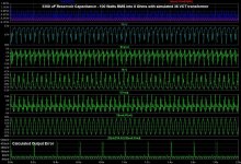
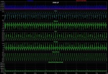
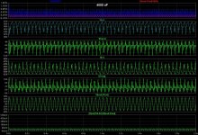
I am simulating with both square and sine signals. I started with low-frequency square waves (25 Hz repetition rate with 4 us edges) and recorded various performance and measurement data for many likely candidate PSU parameter sets (e.g. VA per secondary of 120/240/360, variable capacitance per rail, Rloads of 8 and 4 Ohms, output power levels of 50/75/100/150/200 Watts RMS, but not all combinations of those), while also trying to note what capacitance level was just high-enough to prevent pre-clipping distortion of the output waveform (and recording the deviation of the voltage of the waveform tops).
I am also repeating, with sine waves, many of the VA/output-power/Rload combinations that I had simulated with square waves. With sines, it's very easy to automate finding the "cutoff" capacitance, because I can just set up a batch of simulations with an automatic stepped sequence of capacitor values, and have each simulation calculate the THD of the output sine, and then look for a sharp change in the resulting progression of THD values. In either case, square or sine, I can also easily notice whenever spikes appear in the calculated output error. But, as with the THD, I don't know how much of that might be audible, if it's more than "none". So I will just present the data, which will at least show where the cutoff between "none" and "some" is, and should also show in what (hopefully-)small capacitance range it suddenly changes from none, or a little, to a lot.
Everything does depend on the supply voltage, of course. But there are only two or three very-common transformer voltages that are in the range that would be usable for the output power levels that we are currently discussing. So far, a 36 VCT transformer seems reasonable, if we want to be able to also try using lower reservoir capacitance values, and it will give about 20%-25% voltage "headroom". I can also do something similar with 30 VCT and 28 VCT and others, later, if anyone is interested.
Cheers,
Tom
Hi,
the article is interesting, I agree that no one has explained it well, the relationship between psu and sound.
Unfortunately, the problem can not be treated in terms of "electrical", i mean the power calculations, joules and etc., do not reveal this relationship. the PSRR has nothing to do with the dynamics of the power stage. in the laboratory have a mospower 400w 2x6 powered by battery 12V 40Amp. I used to study and find the relationship. listening is so different that we are not accustomed to hearing. the explanation moves away from traditional measures. must start from the geometry of the sound signals that make up the envelope to see how they are modified by the psu.
or continue with the transformer and a lot of capacitors (does not solve anything, the amp will continue to sound as far as they should)
Regards
Hi,
.......continue with the transformer and a lot of capacitors (does not solve anything, the amp will continue to sound as far as they should)
Regards
Interesting conclusions. I take it that you have joined the ranks of those who believes that an amplifier sounds as good as its supply. Any specific rules or experiences that you would like to share.
Tom, your last set of plots indicate about 57dB difference between the error and the signal and probably inaudible. Would it be safe to say that the rule of thumb could be 1000uF/Amp to remain inaudible. Looks like we are coming back to a rule established in one of the early posts.
Interesting conclusions. I take it that you have joined the ranks of those who believes that an amplifier sounds as good as its supply. Any specific rules or experiences that you would like to share.
I started a thread that talks about the geometry of the signals. the conclusion?
those who are not able to understand, they think that I am a charlatan.
then there are those who understand well, then attack me.
the conclusion is real one. amplifier to modulate the current. values of this modulation (according to the dynamics of the source) shall have a right to reconstruct the sound. this can not happen if the supply rails decreases.
this is actually a sub reverse modulation, perfect to change the shape of the signals, right where it defines their speed. (just it is timbre of instument's)
So the power supply must be stabilized, but this requires a high-speed controller. does not make sense to see the ripple, eg. at 100Hz. looks at the rising edge of a square wave also.
I add...that the psu, decides fidelity in reproducing sounds, especially all the sounds that form their characteristic dynamics.
This is not woodo or market convenience, this is science very clear.
Last edited:
I do not think that the supply "must" be stabilised (regulated)...............So the power supply must be stabilized............
I think that an amplifier PSU combination can be designed to perform very well at reproducing transient signals that approach the Vpeak capability of the amplifier without a stabiliser in or added to the PSU.
There are many non regulated amplifiers on the market that can do that reproduction trick and it is not magic. It is good design.
I contend that your conclusion is flawed !
I do not think that the supply "must" be stabilised (regulated).
I think that an amplifier PSU combination can be designed to perform very well at reproducing transient signals that approach the Vpeak capability of the amplifier without a stabiliser in or added to the PSU.
There are many non regulated amplifiers on the market that can do that reproduction trick and it is not magic. It is good design.
I contend that your conclusion is flawed !
Dear andewT, absolute no problem. just a consideration...
why add capacitors on psu? sure, not regulated, they play.
try to imagine what it sounds like if the voltage does not drop then.
and..What kind of engineer would be me, if I said I do not need a regulated psu fast?
- Status
- This old topic is closed. If you want to reopen this topic, contact a moderator using the "Report Post" button.
- Home
- Amplifiers
- Power Supplies
- Power Supply Resevoir Size