Hi all,
thread starts in parallel with this other
Asynchronous I2S FIFO project, an ultimate weapon to fight the jitter
to discuss the right way to build an adeguate power supply for that project,
but also to discuss the right way to build high performance regulated power supply for DIY DAC.
In the last time I worked on project simulation and finally I developed my idea. The project at a glance:
- 1° stage: CLCRC filter
- 2° stage: bootstrapped series with pre-regulation (a revised Jung super regulator)
- 3° stage: feed-forward shunt regulation
- hi-grade components
The project is op-amp based, so I investigated if there was reason to build a discrete operational amplifier, but finally I concluded that it is better to use a monolithic OA, such as AD797, AD825, OPA627, OPA132 or so. Another story about Stage IV or buffer.
Now I'm working on simulation, then I'll share my project and I'll start to build a prototype.
Any comments or suggestions would be greatly appreciated.
New regulators and LiFePo4 batteries power supply system from post #160
The Well Regulated Power Supply
User manuals
The Well Regulated Power Supply
Last edited:
nice one!! I would have started a thread, but I couldnt do it justice with the time I have available. well i'm certainly interested. can we please have at least 2-4 (minimum) of the regulators with power transistors or followers? perhaps this could be a snap in module for the standard lower current version.
i'm not sure you quite get where I was coming from though, we or at least I, was talking about networks of 25-50 regulators for the ever-growing complexity of the modern dac and it has little to do with the fifo project; which only requires a single regulated DC voltage input or at the most an additional dedicated supply for the clock board and its flipflops. the greater system under discussion involves far more than this.
the highest performance, yet compact solution i've come across so far is more like the Flea type regulator involving a filtered very low noise monolithic reference with a high performance opamp driver/divider. networks of 50 super regulators and matching raw DC supplies are neither needed nor viable IMO. For me the system involves a combination of LiFePO4 batteries and chargers, IC based post regulators, AC input preregs, flea type regs and shunt regs.
Last edited:
Interesting qusp that you note that different supplies in different sections yield the best sound, whilst this is a can of worms because most everyone will argue for the sake of it, which is mostly useless diatribe, can you expand on what you have found works best in your system?
Please note others reading this, I'm not wanting to have arguments about who likes what, listening impressions are subjective, but at least having it documented we may see patterns in differing powersupplies and what sound they produce, this may provide a further way to tune the system to attain what the listener feels suits them best.
Andrea, crack on brother, have read most of your site with wonder, thanks for sharing your findings, look forward to your discoveries.
OT, may chat to you about dc coupling yet........
Thanks,
Drew.
I am curious what the design goals for this project are? What noise levels are you seeking and why the extra design complexity?
I normally try and use an architecture that has an inherently good PSRR so that the PSU is not as big an issue. That being said, things like sag for punch on the bass are much harder to measure and describe/specify.
Tony
I normally try and use an architecture that has an inherently good PSRR so that the PSU is not as big an issue. That being said, things like sag for punch on the bass are much harder to measure and describe/specify.
Tony
Last edited:
I am curious what the design goals for this project are? What noise levels are you seeking and why the extra design complexity?
I normally try and use an architecture that has an inherently good PSRR so that the PSU is not as big an issue. That being said, things like sag for punch on the base are much harder to measure and describe/specify.
Tony
Not a particular complexity:
- 1rst stage, CLCRC filter, to well decoupling regulator from AC and dreastically reduce ripple
- 2nd stage, series regulator, to maintain a steady voltage decoupling supply from load
- 3rd stage, shunt regulator, to reduce noise
- hi-grade components, to add themselves minimum noise, eg. feed-forward shunt needs a precise and stable current sensor resistor, so I prefer to use a 0,02 ppm metal foil resistor rather than a metal oxide resistor
BTW all your comments and suggestions are welcome, i'll keep them in the right consideration developing this project.
Andrea
Hi Andrea,
This are a some years old design of a low noise power supply, the interesting are the topology of the pcb:
Super Buffer
But this article has confused me. They get very low noise and distortion with a simple zener regulated power supply. Well, test is easy and cheap.
Link para Electrónicos
Click on the links and see the articles in english, also see the page two of the LM833 pdf.
Regards.
I am curious what the design goals for this project are? What noise levels are you seeking and why the extra design complexity?
I normally try and use an architecture that has an inherently good PSRR so that the PSU is not as big an issue. That being said, things like sag for punch on the base are much harder to measure and describe/specify.
Tony
for me it was sheer number, only about 25-30% were of absolute highest performance. but i'm talking about a 4 balanced channel sabre dac (each chip needs 7 supplies) with the fifo i2s buffer, dual master clock and spdif input receiver, multichannel usb->i2s convertor, 2 stereo balanced IV stages, MCU, monitor, remote control (wifi and RS232), charger and control circuitry. no getting around the complexity of such a system
Mmmmmm remote via wifi and 232. Very interesting.... Can you pm a link please?
Yes that is going to be one very full box....... Can see why regs are important, esp those slimline ones you have......
I don't have any design ability regarding sand powersupplies so I shall read, learn and probably ask what others consider dumb questions.....I was taught that the dumbest question is the one not asked.....
Maybe this thread's title should be changed - wasn't the idea to discuss specifically regulator types suitable for high performance digital circuits?
I have little doubt that at least the subjective requirements for analogue circuit regulators are very different from those meant to power digital circuits. How this relates to objective parameters is anyone's guess. Per example i wouldn't seriously consider flea-type regulators for analogue circuits but they may be great for digital. Dac chips are a special case as they often require separate supplies for the analogue and digital parts.
Obviously some compromise will be needed due to the number of regulators and space constraints. Maybe a diy version of the popular discrete 3-terminal replacements would be a good idea with shunt regulators only in really critical stages.
Maybe this thread's title should be changed - wasn't the idea to discuss specifically regulator types suitable for high performance digital circuits?
I have little doubt that at least the subjective requirements for analogue circuit regulators are very different from those meant to power digital circuits. How this relates to objective parameters is anyone's guess. Per example i wouldn't seriously consider flea-type regulators for analogue circuits but they may be great for digital. Dac chips are a special case as they often require separate supplies for the analogue and digital parts.
Obviously some compromise will be needed due to the number of regulators and space constraints. Maybe a diy version of the popular discrete 3-terminal replacements would be a good idea with shunt regulators only in really critical stages.
I agree with you that different circuits requires different power supplies.
Btw if you had an ideal supply you could use it either for analogue than digital circuits. Obviously ideal supply does not exists and I have no claim to build it.
But if we accept some compromises we can try to build a good regulator as for analogue as for digital circuits.
I believe that a CLCRC filter is a good way to decoupling regulator from AC, either for analogue than for digital, so I think we can use it in both case.
The second stage, I planned to use a series regulator like Jung super regulator, but now I'm thinking seriously to implement a simple series regulator based on op amp like AD797 or LT1018 and precision reference like AD580 or AD780, preceded by a monolithic regulator like LT1085. From LT1085 datasheet: Line Regulation 0.025%, Ripple Rejection 75 db, RMS Output Noise 0.003%. I think this three terminal regulator is a good choise for pre-regulation and can supply directly op amp, whereas AD797 has a PSRR of at least 120 db. Also AD797 has an Input voltage noise of 0.9 nV/sqrtHz, that guarantees a very low noise level in regulation.
So, I think that's a good starting point either from analogue than digital.
The shunt stage, I'm thinking to use a feed-forward shunt that guarantees a supply noise rejection of about 26 db at lower frequencies.
Maybe this could be a good design to use either for analogue than for digital stage.
I think that in addition to a good design, components choise make the difference.
Andrea
I believe that a CLCRC filter is a good way to decoupling regulator from AC, either for analogue than for digital, so I think we can use it in both case.
^+1 (agreed).
") I've had good results with CRCRC filters before the regulator chip. I'm using several right now. Just be sure to solder small (0.1 - 0.01uF) XLR or COG MLCCs right across the electro leads in each section to also nuke the stuff above the audio band traveling in both directions (from the line and to the line in the case of digital).
I've had good results with CRCRC filters before the regulator chip. I'm using several right now. Just be sure to solder small (0.1 - 0.01uF) XLR or COG MLCCs right across the electro leads in each section to also nuke the stuff above the audio band traveling in both directions (from the line and to the line in the case of digital).Dumb Question Number 1:
What are these things?
I am assuming caps of some sort but clarification would be nice....
Thanks,
Drew.
What are these things?
^+1 (agreed).
I am assuming caps of some sort but clarification would be nice....
Thanks,
Drew.
Guess I'll dig a little deeper here.
When you say "Noise" do you mean transient response or the 120Hz ripple and EMI coming in the AC Line cord.
Tony
About shunt regulation, I mean all undesirable noise coming from previous stage, since it provides a path from the supply voltage to ground through a variable resistance.
Feed forward shunt provides a better supply noise rejection than feedback shunt, although it is more difficult to implement because you must predict the maximum noise to be canceled in the design.
Andrea
Dumb Question Number 1:
What are these things?
I am assuming caps of some sort but clarification would be nice....
Thanks,
Drew.
yes they are types of ceramic cap. MLCC is multilayer ceramic capacitor, Np0 or c0g are the same thing and are tempco ratings. NP0 stands for Negative Positive Zero, meaning that the capacitance does not change over temperature. for c0g it stands for
C = 0.0 ppm/c
0 = -1 (multiplier)
G = 30ppm tolerance over 25-85c temp range
on the other hand adgr your XLR was obviously a typing error and you meant to type X7R which is the same sort of rating but from a different coding system.
X7R
X= low temperature requirement of -55c
7 = high temperature requirement of 120c and
R = +/- 15% tolerance
and you take from that, that c0g is superior (and more expensive than) X7R also you cannot find many large value c0g/np0 caps, they generally top out at 0.47uf/470nf at least for the standard small package leaded and SMD
also adgr: people have been throwing randomly chosen bypass caps at problems for many years so I cant blame you, but it certainly isnt guaranteed to improve matters
Last edited:
and you take from that, that c0g is superior (and more expensive than) X7R also you cannot find many large value c0g/np0 caps, they generally top out at 0.47uf/470nf at least for the standard small package leaded and SMD
Great post qusp and thanks Drew for asking a Not So Dumb Question.
I didn't know the ratings system info, I learned something today!
Hey Hochopeper,
I learnt in Year 7 at school the sting on a bee is in its bum. I was laughed at but now I knew. Course if you asked them capital cities or their times tables, the blank looks one would get would swear they didn't understand the question......
Indeed learnt much from that, what fascinated me most is.......
That's probably all in his head.........I can remember all sorts of stuff, that I'll need to write down......!
Cheers,
Drew.
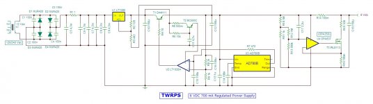
The starting point
After several simulation with different topologies of regulator the following schematic is the starting point to build a prototype.
First stage, rectification and filtering, use a CRC filter to well decoupling regulator from AC.
Second stage is an op amp based series regulator with preregulation using a monolithic IC LT1085. The reference of preregulator is the clean regulated output of the stage, such as in the Jung super regulator. Follows a conventional series regulation implemented by an LT1028 low noise high speed op amp and a classic D44H11. Voltage reference of feedback circuit is an AD780, very low drift 3ppm/°C. Op amp is decoupled from power supply with a 0.5 ohm resistor and a capacitance multiplier.
Last stage is a feed-forward shunt section, consisting of an op amp, a mosfet, a capacitor and a few resistors. This stage reduce the noise about 30 db and improve transient response. Based on a Maxim application note, it can cancel noise up to 1.3 mV. Best choise for op amp should be OPA350, but I'm note sure it can tolerate 6V power supply; data sheet indicates 7V as absolute maximum supply voltage and 5.5V max operating voltage.
I'm still working with simulation, then I'll order components to buld a prototype and test its real performances.
Any suggestions are wellcome.
Attachments
I'm going to write some "Cardinal Rules" for regulators:
1) Regulate the clock Vcc/regulator separately from analog circuitry regulation.
2) Load the regulator for as much current as the pass transistor can handle (heat sinked of course.) If you have to, add a ballast resistor to accomplish this.
3) Don't skimp on trace width.
4) where you think you can use a 1/4 watt resistor use a 1/2 watt resistor.
I would take a look at the layout which Jan did for Jung's regulator and go from there.
- Home
- Amplifiers
- Power Supplies
- The Well Regulated Power Supply