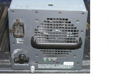
I picked these up from an office sale.
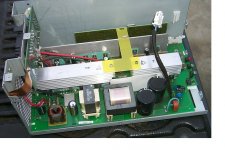
Its got 42V dc X 27 amp, and 12, 5 and 3.3 taps with a few amps each. Obviously it was made to deliver 42vdc.
I am surprised to see such a small transformer and so many transistors, hard to see but the heat sink has like 10 of those.
Anyway hope I can use it or use parts of it for a chip amp project.
Thanks guys and gals.
Cool.
Srinath.
Attachments
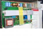
That is definitely a switching supply, no question.
If you had two, you could get +/- 42 V rails, as long as you made sure that the output is floating and not referenced to ground (i.e. the grounded plug). If you can adjust the voltage down to a little below 40 V that would be better (42 V is on the bleeding edge for most chipamps), but if you don't know how, it's probably better not to guess.
Since these rectify and filter the AC mains directly, you must be careful poking around inside. Those big capacitors can have over 170 VDC on them (350 V in 240 VAC countries!). There is sometimes a 'bleeder' resistor across those to drain the charge, but it can take at least several minutes to drain it after pulling the plug. Even still, you should must drain those high voltage capacitors with a large 100 ohm or so resistor across the terminals for several seconds. Don't touch anything until you know the high voltages are drained.
Modify it.
I am not trying to exceed its limits, I am trying to make it a smaller and lighter by eliminating the unneeded if there were any. Maybe that itself a dumb idea, its like making an amp lighter by ditching the heat sink.
I do have a few, and yea I was gonna use 2 for +/- 42 - no problem. The adjustment - I doubt I got the knowledge to do that. However the chipamp I am building is an L20. Easy 42v capable.
I am trying to get it into a slightly better chassis, the ground isn't the negative, I'd be OK I think.
Thanks.
Srinath.
Usually they are designed to meet some special specifications, and has a +-5% adjust (a trimmer inside, but accessible from outside. I´m sorry to tell you that youu can´t modify it more than such limits. I tell you from my repairing and designing experience.
Regards.
I am not trying to exceed its limits, I am trying to make it a smaller and lighter by eliminating the unneeded if there were any. Maybe that itself a dumb idea, its like making an amp lighter by ditching the heat sink.
That is definitely a switching supply, no question.
If you had two, you could get +/- 42 V rails, as long as you made sure that the output is floating and not referenced to ground (i.e. the grounded plug). If you can adjust the voltage down to a little below 40 V that would be better (42 V is on the bleeding edge for most chipamps), but if you don't know how, it's probably better not to guess.
Since these rectify and filter the AC mains directly, you must be careful poking around inside. Those big capacitors can have over 170 VDC on them (350 V in 240 VAC countries!). There is sometimes a 'bleeder' resistor across those to drain the charge, but it can take at least several minutes to drain it after pulling the plug. Even still, you should must drain those high voltage capacitors with a large 100 ohm or so resistor across the terminals for several seconds. Don't touch anything until you know the high voltages are drained.
I do have a few, and yea I was gonna use 2 for +/- 42 - no problem. The adjustment - I doubt I got the knowledge to do that. However the chipamp I am building is an L20. Easy 42v capable.
I am trying to get it into a slightly better chassis, the ground isn't the negative, I'd be OK I think.
Thanks.
Srinath.
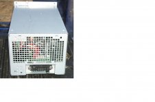
Back together
OK its all back together and nothing caught on fire ... always good that.
So now the pic below - I have a couple questions about that.
The red wire in the fore ground - bottom left of the attached pic is 42v, the black wire next to it is 12v. The red wire toward the center left of the pic is also 42v dc. The black wire just before it is the negative - its not referenced to ground/body.
The 2 42v red wires are not even from the same location in the power supply, and they obviously dont show continuity to each other.
Now can I use this 1 supply to supply the -42 0 and +42 volt DC needed by the l20 amp ?
Thanks guys.
Cool.
Srinath.
Attachments

"Cisco Systems" tells me it's probably a big supply for a rack of networking equipment. Is there any type of model # identifier on the case or pcb? You might get lucky and find some docs online.
Is there 2 grounds, or do they share just 1?The 2 42v red wires are not even from the same location in the power supply, and they obviously dont show continuity to each other.
Now can I use this 1 supply to supply the -42 0 and +42 volt DC needed by the l20 amp ?
A "hot Swap" CISCO Catlyst Power Supply for sure.
This nothing but a PC Power supoply that is used in a "hot Swap" chassis.
...
Nothing specatcular, the Catalyst has the capability of fail safe operation where there are two power supplies. Both are active, and should one fail, the remaining power supply carries the load to keep the computer from failing.
..
They can operate with one, or both power supplies.
..
Dave
Phoenix, AZ
This Forum does not allow discussion of DIRECT ONLINE equipment.
An SMPS that uses mains electricity to directly charge a capacitor is a direct online connection.
If you add an isolating transformer between the mains supply and the input to the smps then discussion would be allowed.
This Thread has been running for 18days.
When is it due to be closed?
Why has some Member not reported the thread?
Last edited:
 thread closed until discussed with other mods more knowlegable than me.
because most people can tell the difference between a linear power supply and a Standard SMPS UL and CSA approved power supply.Why has some Member not reported the thread?
OK can I post in this thread now ?
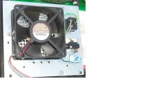
OK I guess I am poking around inside it. However it has a transformer, bridge rectifier, caps and fuses and transistors etc etc before I may split it ... however I have several of these, and some are going to be used unmodified atleast - 2, may modify 1-2.
Cool.
Srinath.
OK I guess I am poking around inside it. However it has a transformer, bridge rectifier, caps and fuses and transistors etc etc before I may split it ... however I have several of these, and some are going to be used unmodified atleast - 2, may modify 1-2.
Cool.
Srinath.
Last edited:
What wold happen if some guy´s want to ask for a AA5? Also will be closed?This Forum does not allow discussion of DIRECT ONLINE equipment.
An SMPS that uses mains electricity to directly charge a capacitor is a direct online connection.
- Status
- This old topic is closed. If you want to reopen this topic, contact a moderator using the "Report Post" button.
- Home
- Amplifiers
- Power Supplies
- What power supply is this and how does it work