Hi
I would like to knock up a simple variable PSU based on a transistor voltage regulator, rather than the usual 78xx / LM317 circuits and I am playing around with the circuit below based on parts I have handy. This seems to work quite well (the drop out voltage is a disgrace but that's not too much of a problem for me).
I would like however to add an LED indication of when the circuit has gone into short circuit limit and I cannot figure out the best way to do this without altering the effectiveness of the voltage regulation or the current limit. It would be nice to have a green LED lit when regulating and switching to a red LED when current limiting. Can anyone help me?
Thanks!
Ray
I would like to knock up a simple variable PSU based on a transistor voltage regulator, rather than the usual 78xx / LM317 circuits and I am playing around with the circuit below based on parts I have handy. This seems to work quite well (the drop out voltage is a disgrace but that's not too much of a problem for me).
I would like however to add an LED indication of when the circuit has gone into short circuit limit and I cannot figure out the best way to do this without altering the effectiveness of the voltage regulation or the current limit. It would be nice to have a green LED lit when regulating and switching to a red LED when current limiting. Can anyone help me?
An externally hosted image should be here but it was not working when we last tested it.
Thanks!
Ray
Thanks for your help godfrey!
Goodness, yes you are right I simmed it and it took around 10secs for the voltage to collapse under 100% overload!! How can I speed things up whilst still keeping a good voltage reference and regulation? should I just remove the caps?
Looks like the LED solution is simplicity itself! I will try this out and see what happens
Cheers
Ray
Hi Ray
Have you checked for stability? It doesn't look promising. TL071 is unity gain stable on it's own, but probably not with that output stage and output filter.
Adding a couple of resistors as shown below should make it behave nicely. The top of the 10K resistor can either go to the output of the TL071 (as shown) or to the top of R2. (and, no, I'm not tripping, that is a resistor, not a capacitor. )
)
Cheers - Godfrey
Have you checked for stability? It doesn't look promising. TL071 is unity gain stable on it's own, but probably not with that output stage and output filter.
Adding a couple of resistors as shown below should make it behave nicely. The top of the 10K resistor can either go to the output of the TL071 (as shown) or to the top of R2. (and, no, I'm not tripping, that is a resistor, not a capacitor.
)Cheers - Godfrey
Attachments
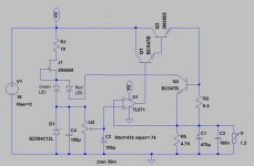
I have downsized my power requirement and therefore the op-amp based circuit seemed a little overkill. I Google’d for a simpler discrete regulator circuit and found this which seems to work very well for a simple circuit.
I would like however to have the LED traffic light indication of current limit that godfrey implemented on the op-amp version as this worked perfectly. Can this be done also with this circuit and the lower load and trip currents? if so, then how as I have tried and failed!!
Any improvements in component values etc would be appreciated as again I have used the transistors that I have to hand rather than understanding what is going on in the circuit!
Cheers
Ray
An externally hosted image should be here but it was not working when we last tested it.
I would like however to have the LED traffic light indication of current limit that godfrey implemented on the op-amp version as this worked perfectly. Can this be done also with this circuit and the lower load and trip currents? if so, then how as I have tried and failed!!
Any improvements in component values etc would be appreciated as again I have used the transistors that I have to hand rather than understanding what is going on in the circuit!
Cheers
Ray
I think your GND location is in the wrong place.
How does R1 activate the current limiter?
Is the +reg label, the input for the raw power supply?
The measuring circuit is actually a bridge.
The error signal across the bridge is used to control the Darlington (EF).
Show the bridge as such and ensure when you build it that the bridge is truly maintained as a real bridge with the nodes in the correct places to allow a proper and accurate "error" signal.
Last edited:
Andrew, thanks for your help man, I never looked at it this way!
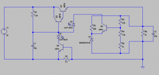
Is the below arrangement what you mean, have I got the bridge elements right and is this what you mean by connecting the nodes correctly?
The current limit seems to work well in LTspice land and I am hoping it will be as effective in reality. The +Reg node is the input from the rectifier, CRC filter, sorry if this caused any confusion
Any ideas how I can implement the current limit LED traffic lights as this is an essential feature for the application and I have drawn a complete blank so far?
Cheers
Is the below arrangement what you mean, have I got the bridge elements right and is this what you mean by connecting the nodes correctly?
An externally hosted image should be here but it was not working when we last tested it.
The current limit seems to work well in LTspice land and I am hoping it will be as effective in reality. The +Reg node is the input from the rectifier, CRC filter, sorry if this caused any confusion
Any ideas how I can implement the current limit LED traffic lights as this is an essential feature for the application and I have drawn a complete blank so far?
Cheers
I think the GND is still in the wrong side.
Virtually no current flows through R1. It cannot monitor output current and thus cannot trigger on excess output current.
I see you have copied the latest Salas style for the sense leads. Just be sure you actually build it to match the schematic. The DCB1 is completely wrong when transferred from schematic to the PCB.
Thanks Andrew, appreciated!
I will design the PCB to reflect the schematic with sense nodes and hopefully this will behave well. The GND is just where it is for the purpose of simulation. R1 is just in the negative supply from the Rectifier and so will work in a conventional manner and simulates very well with overload.
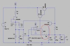
I would also like to know the exact role of C1 and it's bearing on the regulation. Is this just to stabilize the bias point for the Darlington pair as the smaller the value for C1, the faster the circuit reacts and current limits. I would like to optimize this part for the best performance trade off if possible. The original circuit specified 100uF here, but this made the current limit slow, as godfrey pointed out in the original op-amp version regulator. I chose 10uF here but could this be improved?
I have also still got nowhere with the LED indicators, do you know of a way of adding these? Even if it means adding more transistors/complexity, the indicators are essential for my needs and if I cannot implement them with this circuit then I will have scrap it and keep looking!
Can anyone help?
Cheers
Ray
I will design the PCB to reflect the schematic with sense nodes and hopefully this will behave well. The GND is just where it is for the purpose of simulation. R1 is just in the negative supply from the Rectifier and so will work in a conventional manner and simulates very well with overload.
I would also like to know the exact role of C1 and it's bearing on the regulation. Is this just to stabilize the bias point for the Darlington pair as the smaller the value for C1, the faster the circuit reacts and current limits. I would like to optimize this part for the best performance trade off if possible. The original circuit specified 100uF here, but this made the current limit slow, as godfrey pointed out in the original op-amp version regulator. I chose 10uF here but could this be improved?
I have also still got nowhere with the LED indicators, do you know of a way of adding these? Even if it means adding more transistors/complexity, the indicators are essential for my needs and if I cannot implement them with this circuit then I will have scrap it and keep looking!
Can anyone help?
Cheers
Ray
AndrewT is both right and wrong about the ground being "on the wrong side".
Basically, you need the return current from the load to flow through the 2.7 ohm resistor. You can call the bottom leg of the load "ground" if you want to, and you can connect it to earth ground if you want to. But the negative side of the power supply can't connect here. It needs to be connected to the other side of that sensing resistor.
Adding LEDs is not so hard once you understand the principle of operation of this regulator. R6 (in your circuit, mine has different component numbers) provides the current to turn on the darlington output transistor. The voltage is regulated by stealing some of this current, through either the voltage regulation circuit (formed by Q4, D1, etc.) or through the current regulation/limit circuit (formed by Q3 etc.). When in "constant voltage" mode, current will flow into the collector of Q4, but none into collector of Q1 since the current limit hasn't kicked in. When in "constant current" mode, current will flow into collector of Q1, but none into Q4 since the voltage reg is trying to increase the voltage but can't. The easiest way to add LEDs is to put them inline with the collectors; they will light when current flows. I tweaked R6 to allow more current for brighter indicators. Try this out by changing the load; you will see that there will be current through one LED or the other based on voltage or current mode.
See attached for LED locations and power supply connection. (Note again the component numbers mentioned above do not correspond with the schematic attached here).
Attachments
This is a standard voltage regulator circuit built by especially the Japanese in the 60's and 70's probably in millions.Mostly used to power 12V CB radios and such.
Note that the circuit as shown cannot go below about 7V.
I don't agree with macboy's description of how it works at all.In fact I find it strange.
Note that the circuit as shown cannot go below about 7V.
I don't agree with macboy's description of how it works at all.In fact I find it strange.
I don't agree with macboy's description of how it works at all.In fact I find it strange.
Please offer your description.
Thanks macboy!! This nearly looks like the solution (I could have sworn I tried both those positions for the LEDs but to no avail!!!) I tried the sim with the LEDs and at 35V input everything works as you described and LEDs get the current they require in each regulator state. However Q1 dissipation at 200mA load is quite high and pretty hairy under current limit conditions.
It was my intention to power the circuit from around 15V to keep the dissipation within easy limits but at this input voltage the "OK" LED in Q4c only sees around 1.5mA or so and therefore will be quite dim. I tried to reduce R6 from 3.3K to 1.5K to see if this improved the matter but the regulation suffered. The circuit is for a 9V output, I included the trimmer to tweak the voltage should this be necessary, but I suppose the ability to go to 12v would be nice but not essential. Do you have any ideas?
Thanks Rolf, your post is interesting, and seems to suggest that this circuit maybe not be too well suited to low current requirements, is this the case? It is funny, I thought the schematic had a look of Japanese origin about it, but out of all the simple transistor based circuits I tried to sim, this one seems to have the best regulation (around 0.3% from 0 to 200mA) and so it would be nice to be able to tweak into the ball park.
Really appreciate the help you are giving me!
Cheers
Ray
Thanks macboy!! This nearly looks like the solution (I could have sworn I tried both those positions for the LEDs but to no avail!!!) I tried the sim with the LEDs and at 35V input everything works as you described and LEDs get the current they require in each regulator state. However Q1 dissipation at 200mA load is quite high and pretty hairy under current limit conditions.
It was my intention to power the circuit from around 15V to keep the dissipation within easy limits but at this input voltage the "OK" LED in Q4c only sees around 1.5mA or so and therefore will be quite dim. I tried to reduce R6 from 3.3K to 1.5K to see if this improved the matter but the regulation suffered...
Are you familiar with the uncertainty principle in physics? Basically, you can't observe somthing without affecting it. This is true in electronics too, you can't measure a voltage or current without affecting the circuit under test. By adding the LED, you affect the regulator since the minimum voltage of the base of Q2 is now ~2 V (VF of LED) higher than before. An alternative could be to fit a small resistor and use a comparator or op-amp to detect current flow through the resistor by looking at the voltage across it.
I decided to scrap and go back to the op-amp based regulator topology as I needed the LED indicators. I found the following, more conventional arrangement, and I think managed to add the "traffic" lights feature via a couple of transistors. The circuit seems to work very well indeed in simulation but would anyone kindly look over it to see if there is any issues with it, circuit stability etc, incorrect component values etc. The overload Red LED is D3 via Q4 and the normal Green LED is D2 via Q5.
Your expert input will be much appreciated before I start getting the circuit together for tests
Cheers
Ray
An externally hosted image should be here but it was not working when we last tested it.
Your expert input will be much appreciated before I start getting the circuit together for tests
Cheers
Ray
- Status
- This old topic is closed. If you want to reopen this topic, contact a moderator using the "Report Post" button.
- Home
- Amplifiers
- Power Supplies
- Simple linear reg short circuit LED