Can't you block the DC with a cap?
Yes that's what I do. AP output > cap > reg output.
The cap must be pretty big if you want to measure accurately to low freq, but a 1000uF 25V electrolytic is cheap & probably in your junk box anyway. We're not interested here in super-duper caps anyway.
Alternatively, you could modify the AP zout measurements script to measure Vgen before the cap to calculate Iout, and with the other channel measure signal at the reg output and calculate Zout.
jd
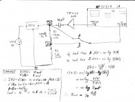
Guys, may I have your attention for a bit? I don't have access to an AP unit but have an old HP 3585A spectrum analyzer. It doesn't have two channels, so I can forget about phase measurements. It would be nice though to at least get a measurement of the output impedance magnitude.
This is what I have in mind. The 3585A has this feature that one trace can be saved in memory and then subtract it from a new trace. Say, measure trace A, the AC voltage across a one ohm resistor, so that this is actually the AC current induced in the load by the tracking generator, which is coupled to the load via a power amp (truepath TA2024 class-d little amp) and capacitor. Then save this to memory as trace B. Then measure a new trace A as the AC voltage component across the load. Since the values of A and B are logarithmic, their difference is actually voltage/current division, the "impedance." I'm thinking that a 3Hz resolution BW, while not ideal, is adequate.
I've tried it and it works indeed, meaning that I was able to get a reading for (A-B) for a lm317 and a 7812. But I'm just not sure that my interpretation of the final (A-B) result is correct. The nice feature is that after the cables are hooked up the actual measurement is very easy and fast to do, and in the case of this spectrum analyzer, it can be run to well beyond audio frequency.
The attached drawing shows the setup.
Any comments are very welcome.
Attachments
Guys, may I have your attention for a bit? [snipped to save bandwidth]
The attached drawing shows the setup.
Any comments are very welcome.
Nice idea!
I think what you want to measure as current is the current through a resistor feeding the amp output into the reg output, rather than the current through the resistor as shown. You want to know the current that is 'absorbed' by the reg (the virtual Zout).
You can do that by measuring the generator (amp) Vout and divide by the serie resistor, as the Vac at the reg output will be much lower than the amp Vout so the error is very low. Say you set Vout at 10V, Rseries at 100 ohms. Neglecting the low (mV's) of ac volts at the reg output, Iout is 100mA ac. Store this trace in dB.
Then measure the ac volts at the reg output, store as trace in dB, and subtract the two traces.
There's one problem I see, and that is that dB are a ratio, not an absolute value. The difference curve will show you how Zout varies with freq, but not the actual value. So you need to do an absolute measurement at a spot freq to calibrate your setup.
Say your ac signal at the reg output, at 1kHz, is 1mV. You know that the Zout there is 10 milliohms. So you now know that the point where your difference curve goes through 1kHz is actually 10 milliohms. The rest is easy
")
jd
Jan, thanks, I'll try your suggestion. Regarding the dB though, the HP can give dBV, which is relative to 1V (it can also show dBm). That should be calibrated already, no?
Unfortunately I don't have a HP-IB card, as they seem to go for some big $$ even used on eBay. Would have loved to be able to get all this done from a PC, and then do any post processing easily.
Unfortunately I don't have a HP-IB card, as they seem to go for some big $$ even used on eBay. Would have loved to be able to get all this done from a PC, and then do any post processing easily.
Last edited:
Jan, thanks, I'll try your suggestion. Regarding the dB though, the HP can give dBV, which is relative to 1V (it can also show dBm). That should be calibrated already, no?
Unfortunately I don't have a HP-IB card, as they seem to go for some big $$ even used on eBay. Would have loved to be able to get all this done from a PC, and then do any post processing easily.
Yes that should help, not sure about the actual scale settings available. Can you chnage scale legends?
Check out the USB HPIB adpater from Prologix, LLC || Home great value for 150 $ or so!
jd
Yes that should help, not sure about the actual scale settings available. Can you change scale legends?
Check out the USB HPIB adpater from Prologix, LLC || Home great value for 150 $ or so!
jd
Yes, the display can be changed to V, dBV, dB, and dBm. The reference can also be changed. But the trace on the screen stays in the log domain. The marker only shows different unit values. Of course if I could extract the values into a PC the rest is easy as 1,2,3.
The GPIB-USB seems very nice, so I could do everything from my laptop, that'd be great.
The other thing about this setup is that I could insert in the loop a low noise amp with 20/40/80 dB.
I'm very tempted to put one of these together in a hurry. I got all the parts, except for the GPIB cable and socket, which are probably going to cost more than the rest.
http://www.webalice.it/hotwater/PicPlot.htm
Edit: AND they have a USB version too. I'm drooling...
http://www.webalice.it/hotwater/USBpicplot.htm
http://www.webalice.it/hotwater/PicPlot.htm
Edit: AND they have a USB version too. I'm drooling...
http://www.webalice.it/hotwater/USBpicplot.htm
Last edited:
I'm very tempted to put one of these together in a hurry. I got all the parts, except for the GPIB cable and socket, which are probably going to cost more than the rest.
http://www.webalice.it/hotwater/PicPlot.htm
Edit: AND they have a USB version too. I'm drooling...
http://www.webalice.it/hotwater/USBpicplot.htm
In that case you'd also want Ulrich Bangert's EZ-GPIB utility.
Downloads
jd
Good one! Another one that seems useful might be the open-source GPIB toolkit. As soon as I get the circuit working I'll report what happened.
Here's the two setups I am using -- the opamp is a OPA544 at the moment, I am going to switch it out for an LME49600 -- I ran one experiment with it yesterday (then took my wife to see Die Zauberflaute in the afternoon).
http://www.tech-diy.com/TestEquipment/Impedance/VI_Method/Schema.gif
http://www.tech-diy.com/TestEquipment/Impedance/VI_Method/Schema2.gif
You set the Generator such that the voltage across R13 (RSense) is 5mV @1kHz = 50mA.
Z = [Vout/V(Rsense)/RSense)] - RSense
Of course, you can get really precise, but the accuracy for #1 is dominated by whether you can measure RSense value to better than a few microOhms!
For the second, you can program the generator to measure the voltage across the sense resistor and use Newton-Raphson or some other iterstive method to set Vgen such that I = 50mA
OPA544's now go for $13 each, anyone say "OUCH"!
Is there a reason not to use a cheapo like a tda2030, tda2006, etc?
For me it's difficult to accept the accuracy of such low absolute figures (around or below one microvolt). I would have an easier time accepting relative measurements, such as output impedance vs. frequency measurements for a few regulators, all measured with the same setup, if possible in the same session.
As you say, the 0R1 sense resistor would have to be measured/chosen within micro ohms accuracy. Whatever you use to amplify the voltage across 0R1 would also need to have accurate gain. Hairy stuff.
Is there a reason not to use a cheapo like a tda2030, tda2006, etc?
I don't think so, but haven't looked in detail at what the noise performance is going to be like. I will eventually, so stay tuned
TDA2030's are just too cheap not to do something useful with...I just don't get it. Why do you need the amp and the Rsense?
The AP has enough output, and the Rsense is internally the AP Zout.
jd
Yes, outside of the AP's box itself the voltages become difficult to measure. For 1 micro-Ohm Z with 50mA of perturbation current, the level which must be measured is 50nV. Looks like you measured 2u Ohm @20Hz in Chart 20B of the 2/95 article in The Audio Amateur, or 100nV.
I finally was able to measure the AD825 Jung Regulator with the pre-regulator -- @10Hz -- 2.7u Ohms -- which seems consistent with the article. The GenMon level changes with the impedance of the regulator. Just have to remember to discharge the electrolytic before connecting the regulator. I have one very, very low leakage cap but it's only 1,000uF @30V.
Last edited:
Now, I try to replicate it, and can't get the same result. I appreciate what my wife does in the lab for a living, and the number of papers she has written in peer-review journals! when I told her of the issue she said "Oh, micro-Ohms, maybe the relative humidity changed".
Hint, hint -- opamp rolling is NOT a good idea
Hint, hint -- opamp rolling is NOT a good idea
How big the difference? Might be something simple, a ground problem, some guy next door using his electrical lawn mower, etc?
Yes, it's been a long time and I don't remember all details, but I do remember that I had to play around with gnd points, wire dressing and such to get those results. At those levels everything has an influence, it seems.
Also things where you pick off the feedback point for the error amp, at that exact point is where you need to do the measurement. But you know that of course.
That said, I would think that 2u or 2.7u is essentially same result.
jd
[snip] Looks like you measured 2u Ohm @20Hz in Chart 20B of the 2/95 article in The Audio Amateur, or 100nV.
[snip]
Jack, I looked at the original 1995 article again and I measured 20 u ohms at 20 Hz, not 2 u ohms. So your 2.7 u ohms is a lot better.
On the neg regulator I measured a lf Zout of 40-50 u ohms.
jd
Is this the chart to which you're referring? -- figure 20a with 20u Ohms in Red (or is the scale on the Y-Axis Volts?, not scaled to Ohms?)
I don't have any AD848's, but a few more SMT AD797AR's.
An externally hosted image should be here but it was not working when we last tested it.
I don't have any AD848's, but a few more SMT AD797AR's.
Last edited:
- Status
- This old topic is closed. If you want to reopen this topic, contact a moderator using the "Report Post" button.
- Home
- Amplifiers
- Power Supplies
- Super Regulator, collecting the facts