Peranders,
As long as you can grade the AD797 to your circuit it will be ok, however a 50% yield is to expensive for me.
Andy,
I have a bunch of OP37 AZ's but their not stable either. You have a gain of about four or more. So that why I use the OP27's but I will populate the board with AD825's.
Now all I have to do is get rid of conducted radiation from my PS audio CD transport
If I'll get 50% yield something is very wrong in the design and I'm going to see to this will never happen. 99.7% yeild is my goal.jewilson said:Peranders,
As long as you can grade the AD797 to your circuit it will be ok, however a 50% yield is to expensive for me.
While reading here http://tangentsoft.net/audio/opamp-linreg.html, I noticed the 2000 Jung revisited version is different from the EDN one.
One notices the extra PNP (for positive version) driven by the opamp.
Any reading material on this development; why was this extra bjt included (error is multiplied with even more gain) ?
One notices the extra PNP (for positive version) driven by the opamp.
Any reading material on this development; why was this extra bjt included (error is multiplied with even more gain) ?
Re: Why not follow Walt´s advices
I changed to AD817 as suggested by Jung. I wasn't seeing any issues with the AD797, but I wanted to use them in a different application for which they were much more suited and I had a bunch of the AD817. Works great.
Listen to Walt. He knows what he's saying. Trust me ...")
And no, I'm not with the government
mlloyd1
PS - And I never tried the neutralizing cap with the AD797. I wish I had, Scott's papers on the AD797 were interesting reading.
I changed to AD817 as suggested by Jung. I wasn't seeing any issues with the AD797, but I wanted to use them in a different application for which they were much more suited and I had a bunch of the AD817. Works great.
Listen to Walt. He knows what he's saying. Trust me ...
And no, I'm not with the government
mlloyd1
PS - And I never tried the neutralizing cap with the AD797. I wish I had, Scott's papers on the AD797 were interesting reading.
Nicke said:... Why not use the AD825 or AD817 as Walt suggested in the articles ...
Nicke
All things old become new again
"Q2 allows the error amp to bias the pass transistor very fast, improving the ripple and dynamic performance. As the load varies at the error amp inputs it will change the current flow for the base of Q1."
The additional follower does drive the output with a lower impedance than the open loop output impedance of the op amp alone helping to move the additional phase shift from the output transistor to a higher frequency. It also increases the linearity of the op amp since the impedance that output of the op amp sees is higher by a factor of the Hfe of the buffer transistor. "In loop"buffers have been used for audio op amp circuits for quite some time now to decrease distortion by greatly increasing the impedance the op omp
output stage has to drive.
Interesting the second Sulzer article, "Regulators Revisited" TAA 1981, used a follower buffered pass transistor for higher current applications. It was not recommended unless needed for high current applications due to the stability concerns caused by the slow pass transistors used. This is not the case for the output transistors used in the newer regulator designs, which have an Ft of 10 to 30 times higher than transistors like the 2N3055. This article also suggest the use of a three terminal preregulator. Is a tribute to Mr. Sulzers work that the state of the art designs for audio regulators so closely resemble topologies developed nearly a quarter of a century ago.
Andy, you are almost right on target here. I get an oscillation from about 90 mA load at 6 MHz! A small LP-filter is necessary for the supply voltage of the AD797. I have tested 4.7 ohms + 100 nF. Without this filter I have a steady oscillation at no load except for the feedback and the reference.andy_c said:So what does this overly optimistic analysis tell us? Well here's an amplitude and phase plot of the simple RLC circuit showing the roughly 18 dB of attenuation at 10 MHz. Now if you have the AD797 data sheet handy, look at figure 14, open loop gain and phase vs. frequency. We have unity feedback because of the capacitor bypassing the feedback resistor. If we look somewhat below 10 MHz, we see in the plot below that there's about 50 degrees additional phase lag. This is also right where the phase of the AD797 starts to look squirrely too. So eyeballing it a bit, it looks like the unity loop gain frequency will be about 7 MHz and the phase margin will be about 10-20 degrees. Not good.
With this filter AND without 100 nF at the output the regulator works very nicely.
peranders said:(...)I get an oscillation from about 90 mA load at 6 MHz! A small LP-filter is necessary for the supply voltage of the AD797. I have tested 4.7 ohms + 100 nF. Without this filter I have a steady oscillation at no load except for the feedback and the reference.
With this filter AND without 100 nF at the output the regulator works very nicely.
Interesting, Per-Anders. Thanks for posting that. The super reg topology is a tricky one for sure. Much trickier than it looks like on the surface. If you need a high Q capacitor to bypass the op amp power supply to ground for stability of the op amp itself, then without the series resistor, the darn capacitor loads the regulator output directly, making it want to oscillate. Looks like you've found the fix with the series resistor.
I often wonder after diving into a lot of theoretical BS whether the conclusion will agree with reality. But it looks like if a good model of the load capacitor including ESL and ESR is available, then it's possible to predict stability or lack of it with pretty good accuracy.
I really want to get my measurements done and this is getting really old. Maybe it is time to get Jocko over here to solder for me. There might be some other tricks for optimizing the regulator for high speed op amps. I would use a very fast pass transistor for one thing, with a 5 to 10 ohm base resistor with it. Something with an Ft of 150Mhz or more if possible.
Andy........ "high Q " is the catch. It is interesting that the data sheet recommends using a series resistance for the larger cap when using a low ESR cap of several microfadads in conjunction with a 0.1 uF ceramic for decoupling the AD797. As for modeling something like this....... I would not get to hopeful in that department. Op amp Spice macromodels are very crude and most probably don't model PSRR. Even if they did, things like capacitive and inductive coupling in the PCB board would require an incredible amount of work and many more measurements than those required to try an RC filter.
Andy........ "high Q " is the catch. It is interesting that the data sheet recommends using a series resistance for the larger cap when using a low ESR cap of several microfadads in conjunction with a 0.1 uF ceramic for decoupling the AD797. As for modeling something like this....... I would not get to hopeful in that department. Op amp Spice macromodels are very crude and most probably don't model PSRR. Even if they did, things like capacitive and inductive coupling in the PCB board would require an incredible amount of work and many more measurements than those required to try an RC filter.
Fred Dieckmann said:The use of a high Hfe pass transistor or even an additional follower between the op amp and the pass transistor is worth investigating ( big hint.......fet). The less output current the op amp has to deliver, the more linear the regulator is and lessit modulates its own supply voltage terminals
Sure I will say something stupid here, but what about a Mosfet as a pass transistor ? Sure the dropout will be higher, but the current delivered by the opamp will be very low.
But I surely miss important points here, such as fet's capacitances and so on... Tell me...
The original idea from Mr Jung I believe, was low noise AND low output impedance and a mosfet has higher output impedance than BJT. I'll guess that you also get a slower output stage so the benefit of a "electronic" capacitor will be less. An advantage though, it's easier to get more current out of the regulator.
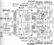
A more original is from Kaneda 1977 and he used parts which were available at that time. 1977 the 709 was "hot" but he had also 741 to choose from.
If you compare Walt's design with this earlier you'll see small enhancements but important ones.
1 Better opamp
2 Better reference
3 Better output transistors
4 LP-filter for the reference
5 Current generator for the pass transistor driver
6 "Sense" connections
7 Pre-regulator
8 No current limitation (if this is better... lower output impedance anyway and that is good)
9 Better resistors
10 Better pcb(?)
Attachments
peranders said:
Andy, you are almost right on target here. I get an oscillation from about 90 mA load at 6 MHz! A small LP-filter is necessary for the supply voltage of the AD797. I have tested 4.7 ohms + 100 nF. Without this filter I have a steady oscillation at no load except for the feedback and the reference.
With this filter AND without 100 nF at the output the regulator works very nicely.
The original series in AA by Jung/Didden/Galo said that the 797 is tricky to get stable in this application. Later follow-ups in letters etc emphasized this. I have always said that the 797 is NOT the best choice for a super regulator, and explained why. Yet, people still select it from the datasheet because it has low distortion . The 797 uses internal positive feedback to get the low THD. That spells "oscillations". But sure, go ahead.
Jan Didden
I used the AD797 because I felt for and with this little filter I get a stable regulator but then again it's a free world and you the use the opamp you want, even a 741! Jan, nothing stops you really from using any other opamp as long as it's good enough and with the right properties.
Andy, I do listen but this doesn't mean that I have to follow the advices.
Andy, I do listen but this doesn't mean that I have to follow the advices.
The SMD and the pcb may have influence on this, meaning more optimal environment if SMD is used.janneman said:The original series in AA by Jung/Didden/Galo said that the 797 is tricky to get stable in this application.
BrianGT, how about your super regulator, did you succeed?
http://www.diyaudio.com/forums/showthread.php?postid=246124#post246124
Re: Its a small world after all ............
I think the main difference between those two is the output stage.
Mr. Kaneda's circuit is exactly as Jung's excluding the improvements. I'll guess you are joking?Fred Dieckmann said:I think the Sulzer design is a much more solid foundation to build on for very good regulator design than Mr. Kaneda's implementation
I think the main difference between those two is the output stage.
peranders said:
The SMD and the pcb may have influence on this, meaning more optimal environment if SMD is used.
BrianGT, how about your super regulator, did you succeed?
http://www.diyaudio.com/forums/showthread.php?postid=246124#post246124
Indeed. That new Mercedes I say just a few minutes ago is basically *exact* the same concept as the T-ford. And per-anders, I get really tired from explaining that the 797 is internally really special, that that is the reason for its problematic behaviour in very high loop gain applications like this. I don't see that SMD or PCB changes the internal construction of this chip? You are certainly free to use *any* amp you want, but giving advice to people based on badly selected parts because you refuse to do your homework I think is not really helpful.
Jan Didden
ALW's pcb is highly regarded by Fred and others and from what I know he recommends AD797, so does aos. I may very likely test other opamps later but now I will concentrate on AD797. Personally I would have never chosen AD797, rather one "normal" general purpose oapmp, like OPA134, or AD8610 or somehting but I have decided to let AD797 have a go.janneman said:You are certainly free to use *any* amp you want, but giving advice to people based on badly selected parts
Jan, why don't you test my pcb and see if you dump into problems? It never hurts to lift up problems or potential problems but those potential problems may not be problems in real life.
I should also add that my pcb's have 50 um copper and everybody else have 35 um (1 oz), positive when it comes to high performance. I'm alone in this, am I?
Typing and laughing don't mix.
The problematic nature of the AD 797 for this circuit has been discussed in print (Audio Electronics) and on the forum. Yes, it can be made to work but it is even more likely to cause problems, and problems of a nature that someone without a fast scope and experience in parasitic oscillations might find difficult to fix. Didn't you recommend a mod to your circuit to address just such a concern?
I am glad to hear about the increased PCB copper thickness. The correct routing and placement of the sense lines is designed to compensate for trace resistance in the load current traces. If this is done correctly, a change in resistance of the traces should be pretty well buried by the effect of the feedback. The impedance of the output transistor dominates the trace resistance by several orders of magnitude for the output (the one that is not ground) at any rate. Perhaps the thicker traces are beneficial to those soldering all those SMT parts by hand.
- Status
- This old topic is closed. If you want to reopen this topic, contact a moderator using the "Report Post" button.
- Home
- Amplifiers
- Power Supplies
- Super Regulator, collecting the facts