This "regulator" is basically a big Vbe multiplier.
I hesitate to call it a regulator, because it is uncompensated, and suffers from the raw tempco of ΔT°/T°abs, ~=-0.35%°C.
But when all is required is to clean up a supply without too much accuracy, it does the job, cheaply, simply and effectively.
The parts are not critical, and only one HV device is needed, the shunt element.
It is versatile, and the basic circuit is a one-size-fits-all, from µpower (<1mA) to high power (several hundreds mA).
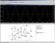
The first pic shows the schematic and the output voltage, with the current swept from 200µA to ~200mA.
R6 and R2 set the output voltage, in this case 160V. R8 is the sum of C3's esr and a damping resistor, typically 0.33Ω (non-inductive).
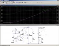
The second pic shows the Bode plot of the regulator itself (green), and its equivalent circuit (bottom right, magenta).
At low frequencies, the residual resistance dominate, but at 40Hz, the 6.4nH inductance begins to dominate, up to about 3MHz, where only C3's damping plays a role.
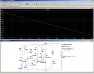
The third pic shows the impedance in the ripple region, where it is the most effective: at 120Hz, the impedance is ~5µΩ.
Within the audio band, things begin to seriously degrade, with the impedance reaching ~800µΩ at 20KHz. But in absolute terms it is not that bad.
It cannot compare with top class regulators, but it is still useful for many applications.
At higher frequencies, things degrade further until approx. 3MHz, where only a mere damping is provided.
Next is the temperature plot: the variation is huge, but it is linear and predictable, and in many cases, having a negative tempco is desirable.
As I said, the components are non critical. The MOS type shown is for simulation only, IRF610 and IRF620 were actually used, but many other similar types would do.
I wasn't able to verify the performances of the physical circuit, it would require a specially made test-bed.
In practice, the actual performances will be dictated by the care brought to the construction.
One important thing to be noted:
the circuit being µpower, all internal nodes are high impedance, and must be carefully shielded against external interferences
I hesitate to call it a regulator, because it is uncompensated, and suffers from the raw tempco of ΔT°/T°abs, ~=-0.35%°C.
But when all is required is to clean up a supply without too much accuracy, it does the job, cheaply, simply and effectively.
The parts are not critical, and only one HV device is needed, the shunt element.
It is versatile, and the basic circuit is a one-size-fits-all, from µpower (<1mA) to high power (several hundreds mA).
The first pic shows the schematic and the output voltage, with the current swept from 200µA to ~200mA.
R6 and R2 set the output voltage, in this case 160V. R8 is the sum of C3's esr and a damping resistor, typically 0.33Ω (non-inductive).
The second pic shows the Bode plot of the regulator itself (green), and its equivalent circuit (bottom right, magenta).
At low frequencies, the residual resistance dominate, but at 40Hz, the 6.4nH inductance begins to dominate, up to about 3MHz, where only C3's damping plays a role.
The third pic shows the impedance in the ripple region, where it is the most effective: at 120Hz, the impedance is ~5µΩ.
Within the audio band, things begin to seriously degrade, with the impedance reaching ~800µΩ at 20KHz. But in absolute terms it is not that bad.
It cannot compare with top class regulators, but it is still useful for many applications.
At higher frequencies, things degrade further until approx. 3MHz, where only a mere damping is provided.
Next is the temperature plot: the variation is huge, but it is linear and predictable, and in many cases, having a negative tempco is desirable.
As I said, the components are non critical. The MOS type shown is for simulation only, IRF610 and IRF620 were actually used, but many other similar types would do.
I wasn't able to verify the performances of the physical circuit, it would require a specially made test-bed.
In practice, the actual performances will be dictated by the care brought to the construction.
One important thing to be noted:
the circuit being µpower, all internal nodes are high impedance, and must be carefully shielded against external interferences
Attachments
Alternatively, with the bypass caps removed and minimal compensation, the circuit can mimic a zener diode.
The virtual zener thus created is a close approximation to a real one, except it is slower and has ~200µA of leakage current.
It has somewhat degraded performances compared to the filtered version, but it remains much superior to a real zener.
It is also less noisy, and it is also less noisy than a bandgap reference, because the voltage is created by simple multiplication and involves no subtraction.
The first pic shows the performance in the time domain: the ~1mV spikes are created when the regulation is just lost, at the current minimum of 200µA.
No associated CCS has been described, because it is not critical or even required for sufficient ripple rejection, but most types will do, included those described here:
http://www.diyaudio.com/forums/solid-state/173005-improved-current-source-sink.html
http://www.diyaudio.com/forums/solid-state/197104-improved-2w-current-sources-ii.html
In any case, it is important to remember that the construction will determine the final performances: the equivalent circuit is that of a massive silver bar of ~10x10x15mm, and if the physical implementation departs much from that, it will affect the results.
The shielding too is of paramount importance.
Attachments
- Status
- This old topic is closed. If you want to reopen this topic, contact a moderator using the "Report Post" button.