I'm in early stages of considering an electrostatic amp, and I'm considering using panel bias supply for some bias in the amplifier itself as well, but then the supply would have to be regulated - or I'll have to resort to tuning it every time - I don't have very good mains.
So, in essence, what I need is a 1500v regulator, with rather low output load - it is to be used as a reference of sorts. 8mA would be a good overprovision. It doesn't have to be very high-performance, knowing that there's no straightforward way of implementing such a regulator, I'd better use a stack of capacitors on the output.
I don't really know where to look for such a schematic, so I'm asking here. Solid state would be better, but tubes would go as well. The main concern is parts availability - if it's rare, it's no go, I'll better do a stack of 'normal' parts.
Thanks to everyone and sorry for the somewhat silly question.
One way this can be done is with an opamp! You float the opamp and usually a pass transistor on a stack of HV zeners. The opamp never sees more than 20 VDC across it, and the pass transistor can be just a couple hundred volts. It's iffy looking and I've never seen anyone figure out how to protect it from shorts, but if you can avoid those it works very well. I can probably dig up a circuit if you need it.
I'm in early stages of considering an electrostatic amp, and I'm considering using panel bias supply for some bias in the amplifier itself as well, but then the supply would have to be regulated - or I'll have to resort to tuning it every time - I don't have very good mains.
Thanks to everyone and sorry for the somewhat silly question.
What's the problem? - just stack as many MOSFETs as you need, cascode... Built-in high power intrinsic zener will keep your fets safe. Use ceramic pads+heatsink or oil bath for cooling. Cut slots on pcb to keep creepage distances large enough...
I would use shunt type... because too many Joules & few kV - straight way to kaboom...
You can use the almost universally adopted solution to this problem: regulate the converter at the primary. For example PWM if it's a flyback, or simply the DC input power for Royer and similar, if the power to be controlled is modest, which is your case.
The combination of high voltages and linear regulation generally ends in a firework, sooner or later.....
The combination of high voltages and linear regulation generally ends in a firework, sooner or later.....
This site may be informative as at those voltages are high...
Index to IEC 60950
Index to IEC 60950
Depends what you call silent: 100KHz is in principle silent (for most of the people, at least).
And if you object at any residue, a small CLC will remove easily any differential residue at 100KHz.
Common mode could be trickier, but it all depends on whether your supply needs to be fully floating or not.
And if you object at any residue, a small CLC will remove easily any differential residue at 100KHz.
Common mode could be trickier, but it all depends on whether your supply needs to be fully floating or not.
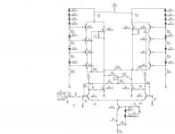
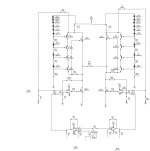
Here are a couple of Class A P-P designs that I have been working on to drive ESL's.
I don't mind sharing these as I don't have the time to invest in them right now.
The opamp drive can be used on the 1000v Output stage with just a few resistor changes in the feedback R34,R35 to 1meg and R6,R2 to 2meg, I think.
The top halves are Constant Current Sources instead of using a load resistor and the current is set by R25,R10 or R15,R22 and/or the number of diodes in the series string of them.
I plan on doing a 3500v version using a MOT to power it some time in the future.
I have built different versions of the opamp drive by stacking 4 IRF510 using it in the 180v range using resistors for the load as I have not tried the CCS version yet.
I have tried every type of IRFXXX fet that I laying around and they all worked with no changes to the circuit.
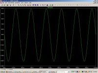
I used a pizeo transducer for a load and it worked great and was very clean.
I thought the driver was going to shatter that I was driving it so hard.
I even played music through it.
I messed with it only for a short time as this was before I had gotten my ESL's running again.
I have simulate a very monsterous Class A power amp using this same configuration into a 2 ohm load.
It just depends on how much current you bias it at.
So, It is on my list things to do (finish) next list.
I have also designed a BJT amplifier that runs on a -/+ 500v supply that should produce 2000 P-P in a BTL configuration.
It was designed in circuitmaker 2000 and runs with no errors.
I have not built that one yet and can dig that one up as well if you are interested in checking it out.
Here is the link to the ones I did try,
http://www.diyaudio.com/forums/head...discrete-class-headphone-amp.html#post2596223
The opamp stage got cut off but it is just a Phase splitter circuit and I can redo the picture if you wish.
I hope this can give you some good Idea's!")
Keep on DIYin' !!!
jer
I don't mind sharing these as I don't have the time to invest in them right now.
The opamp drive can be used on the 1000v Output stage with just a few resistor changes in the feedback R34,R35 to 1meg and R6,R2 to 2meg, I think.
The top halves are Constant Current Sources instead of using a load resistor and the current is set by R25,R10 or R15,R22 and/or the number of diodes in the series string of them.
I plan on doing a 3500v version using a MOT to power it some time in the future.
I have built different versions of the opamp drive by stacking 4 IRF510 using it in the 180v range using resistors for the load as I have not tried the CCS version yet.
I have tried every type of IRFXXX fet that I laying around and they all worked with no changes to the circuit.
I used a pizeo transducer for a load and it worked great and was very clean.
I thought the driver was going to shatter that I was driving it so hard.
I even played music through it.
I messed with it only for a short time as this was before I had gotten my ESL's running again.
I have simulate a very monsterous Class A power amp using this same configuration into a 2 ohm load.
It just depends on how much current you bias it at.
So, It is on my list things to do (finish) next list.
I have also designed a BJT amplifier that runs on a -/+ 500v supply that should produce 2000 P-P in a BTL configuration.
It was designed in circuitmaker 2000 and runs with no errors.
I have not built that one yet and can dig that one up as well if you are interested in checking it out.
Here is the link to the ones I did try,
http://www.diyaudio.com/forums/head...discrete-class-headphone-amp.html#post2596223
The opamp stage got cut off but it is just a Phase splitter circuit and I can redo the picture if you wish.
I hope this can give you some good Idea's!
Keep on DIYin' !!!
jer
Attachments
Last edited:
Much easier to regulate the AC. We got some of these at work:
Line-R - Product Information
Found a supplier that sent us a few of them for $50. Will stabilize AC within +6% and -12%
http://www.apcmedia.com/salestools/ASTE-6Z7V37_R0_EN.pdf
Line-R - Product Information
Found a supplier that sent us a few of them for $50. Will stabilize AC within +6% and -12%
http://www.apcmedia.com/salestools/ASTE-6Z7V37_R0_EN.pdf
Nice FET Thanks!!!!
That would be perfect in my circuit!
Some how that one escaped Searches.
Two of them paralelled in each leg just might do the trick.
8 per amp.
jer
Please be very careful. I cannot stress enough the difficulty of building a safe and robust high voltage regulator. If you have not built a regulator for more than 50V output before, expect fireworks. Remember that any capacitor in the circuit must have a way to bleed the voltage when the circuit is turned off. Anyway... good luck.
The way I would approach this is with a shunt regulator. There are tubes made specifically for this.
Myself I made shunts with EL84 with TL431 in the kathode l;ead, works fine.
Concept could be scaled up but is overkill.
Best idea is just to feedforward some disturbance voltage to a HV tube (with a cascode if needed), should work well.
We are talking about almost zero current! mA's will work good, so big bottles are not needed.
For a electrostat, steady voltage is good (no mains perturbations), the RC takes out ripple too.
albert
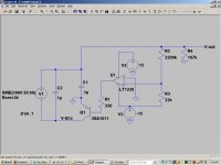
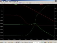
This is a very quiet HV reg, though with pretty wimpy output capability. You'll have to scale it up for the voltage you need and check the dissipation on every part with great care. Expect smoke a couple times until you get it figured out. Maybe take a shot with LTSpice.
Attachments
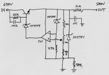
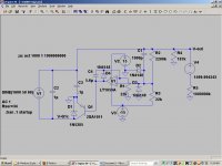
If you can make your 1500V supply floating you could just regulate the ground reference. Then you would only have to deal with the ripple voltage.
(the 187k (R4) is for 8ma load)
You can use just about any op-amp.
(the 187k (R4) is for 8ma load)
You can use just about any op-amp.
Attachments
Last edited:
Thanks to everyone!
Elvee,
Well, then, seems that using an ready CCFL supply + rectifier is feasible. Probably would be the first one to try when it'll come to realisation.
RJM1,
The supply would be an dual-output voltage multiplier if CCFL's won't go, so this is also feasible.
geraldfryjr,
Thanks, the circuits are interesting. I, though, have actually wanted to do an uprated Stax SRX amp with divider coupling between stages for full DC coupling.
- Status
- This old topic is closed. If you want to reopen this topic, contact a moderator using the "Report Post" button.
- Home
- Amplifiers
- Power Supplies
- Simplest regulator for 1500v?