Hi all again,
Ok, i've just introduced this pre-amp to boost signal strengh to my LM3886TF chip amp. In doing so i've got a small "Pop" on power up and a rather strange "crackle pop" two seconds after powering down, which is all coming from the pre-amp stage. Otherwise the pre-amp and amp sounds quiet during operation.
here's the pre-amp, and is powered with a 12VAC-0-12VAC transformer; Wholesale Freeshipping DIY AMF NE5532 stereo preamplifier board #872
I want to build a simple soft start and cut off circuit for the pre-amp and amp transformers (two seperate transformers used). Also to incorporate a signal cutoff from the pre-amp output, to isolate the "crackle pop" sound before it reaches the power amp when powering down. I was going to base the design on this simple soft start circuit i found on a thread on this forum. Probably make some alterations to values and use a muiltiple point relay for what i'll may need to do.
http://www.diyaudio.com/forums/solid-state/2080-dc-filter-9.html#post499280
I was thinking, for the signal cutoff during power down i would use the same relay circuit(different points) to act as a isolation switch for the pre-amp signal output.. Hope i'm being followed correctly. Really, i want to take a simple approach to this. I believe this will deal with the issue.
Also will the relay points induce any noise to the signal if i do go that way about it??
I wonder why you want to use the same relay to soft start the pre-amp and the main amp, at the same time use the same relay for muting the system
You should not be overly concerned with noise creeping into your system at this time
While it may seem simple and cheap to use a single relay for all these functions, it is also a disaster waiting to happen. I would recommend that you use multiple relays as this will save you much grief since you are planning to modify the original design. Relays are easy and cheap to obtain. You do no have to use heavy duty relays for this
Take a look at the spst, spdt, dpst, dpdt relay types and where they are best applicable.
cheers.
Or use a speaker relay delay that gives say 6 seconds before closing on power up and that opens quickly on power off.
Relays in low level signal paths can be problematic unless of high quality or unless you use them to "short" the output of the preamp to ground to provide the mute. That brings problems of its own though (ensuring the preamp can stabilise when the output is grounded) so unless you are aware of the issues I think a "catch all" speaker delay is the easiest.
Why not run the preamp of the main amp PSU too ? A simple resistor/zener regulator is all thats needed for an opamp.
Hi Mooly,
I was also thinking that grounding the signal would be better, i used some 10ohm resistors to ground the signal from the preamp, and it was enough to remove the poppin noises completely. And the first "pop" is instant to the powering up of the preamp, so soft start may be enough to deal with the first "pop" i think, and this also minimise a spike in current through the fuse. And using DPDT relay i can incorporate a signal grounding circuit from the pre-amp output to deal with the second "pop", which is completely removed with that 10ohm shunt to ground.
Whats the speaker relay delay circuit you speak of? is it simple and cost effective?
Also on the dual power supply, A resistor/zener diode can be built to power my preamp? It requires an AC-0-AC supply, can we do it?
Last edited:
Actually, your preamp has its own built in power supply with regulators, so you can apply a DC source as long as there's high enough voltage to overcome rectifier voltage drop and regulator drop out voltage, something like 5 volts or more than the regulated voltage to be sure of proper operation. Also, I agree with Mooly, a single relay with delay to control speakers is all you need, putting relays in the signal path can cause as many problems as they solve. Have a look at this for some ideas: Loudspeaker Protection and Muting
Mike
Mike
Yeah i'm gonna move away from that idea of putting a contact relay switch in the signal path itself, i'm going to try for the ground (short) method with some resistors. I'm going to build and trial my idea, try a few different resistor values, i believe it may be a novel way to deal with the problem. I'll measure and if it works i'll stick with it, if it doesn't i'll take DC detector idea for a test run.
Also about the pre-amp power supply, i have got the second tranny running for it, but how will i go about using my current 25VAC-0-25VAC tranny to drive this. The PSU/rectifier i'm using outputs 36VDC-0-36VDC in to my chip amp, how will i go about powering my 12VAC-0-12VAC pre-amp from this supply?
Also about the pre-amp power supply, i have got the second tranny running for it, but how will i go about using my current 25VAC-0-25VAC tranny to drive this. The PSU/rectifier i'm using outputs 36VDC-0-36VDC in to my chip amp, how will i go about powering my 12VAC-0-12VAC pre-amp from this supply?
If it's already working OK with two transformers, you should just leave it as is, I was just commenting that the preamp board you are using could be run from a DC source if desired. As far as the shorting method, I assume you mean between the preamp output and power amp input? It may fix preamp power up noise, but won't address possible power amp noise, that's why I perfer to use relay switching between power amp and speakers, and as a bonus, makes speaker protection possible.
Mike
Mike
Also on the dual power supply, A resistor/zener diode can be built to power my preamp? It requires an AC-0-AC supply, can we do it?
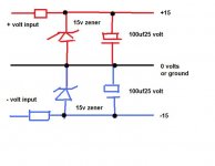
Like this... you feed it from the main -/+ supplies to the main amp.
Attachments
Hi Mike,
yeah i was gonna short the signal between the preamp output and amp input. Or i was just thinking of shorting the power supply on the DC side maybe with the same method. Short + to ground and - to ground using resistors to drain the charge in the caps. I'll try that one too.
If there is an easy way to use one tranny to power both i would like to do that. Mooly suggested a zener/resistor circuit, but i wouldn't know how to go about that.
rick
Hi Mike,
yeah i was gonna short the signal between the preamp output and amp input. Or i was just thinking of shorting the power supply on the DC side maybe with the same method. Short + to ground and - to ground using resistors to drain the charge in the caps. I'll try that one too.
If there is an easy way to use one tranny to power both i would like to do that. Mooly suggested a zener/resistor circuit, but i wouldn't know how to go about that.
rick
Hi Richard, I'm sure Mike will say the same as me on shorting PSU's to discharge them. It's a definite NO
The PSU I posted a few minutes ago... it really is that easy.
The ground is the main ground in your chip amp. The - and + inputs are from the main reservoir caps... so it just connects across your -36 - 0 + 36 rails.
The resistor is chosen to allow a few millimaps to flow through the zener... if you tell us how many opamps it's feeding in the preamp we can work the value out. It's very non critical though.
I've just looked at your link in the first post.
The PCB has on board regulators. So we can still retain those. It says they are 78/7912 type.
The only difference to my circuit is that we would choose a higher zener voltage, say 18volts and feed the original connections on your board. You can feed DC into the bridge rectifier with no problem.
The PCB has on board regulators. So we can still retain those. It says they are 78/7912 type.
The only difference to my circuit is that we would choose a higher zener voltage, say 18volts and feed the original connections on your board. You can feed DC into the bridge rectifier with no problem.
Now i do!!
So that diagram, thats not from the 240VAC mains is it??? No it's from the secendary AC side of the tranny?? or the DC side of the rectifier?
That post slipped in... I didn't see it
Yes its fed from the DC side of the rectifier, the -/+36 volts
The resistor is chosen to allow a few millimaps to flow through the zener... if you tell us how many opamps it's feeding in the preamp we can work the value out. It's very non critical though.
How many opamps?? there's the pre-amp feeding the two mono chip amps boards, one for each channel.
And shorting the caps is a no no, haha i just tried it with two 33ohm resistors, 33ohm + to ground, 33ohm - to ground. What would happen if i was to continue going about it in this manner?
Anyway i just finished the circuit and all seems to be a success. The start up "pop" has turned to a slight cone movement(i'll tweek a little), and the nasty sounding power down "pop" is completely gone. Allthough i'm shorting the caps at the moment to solve the last "pop" issue.
I hadn't looked at the photo of the preamp when I asked that... a single 5532 draws around 10milliamps give or take.
Shorting the rails is a no no... what caps are you shorting ?
It's not clear what you are doing
The caps i'm shorting are those 4x 50V 10,000uf on the PSU board i previously pinned up on my other posts. I'm using 33ohm 5W resistors, i tried it manualy with no spark on contact and the resistors remain cool. What would i be damaging in doing this, i've previously seen caps explode with over volt stress. I would have thought it would have been Ok to do this to quickly drain the remaining charge in the caps.
Your not damaging anything with 33 ohms 5 watt resistors across the 10000 uf caps... although personally IMO it's not a good way of overcoming the problem.
I'm still not 100% sure whether you mean you have the resistors connected permanently or just that they connect via a relay when the power goes off.
The zeners... it works like this. 36 volts to begin with. The 7812/7912 regulators need around 15 to 25 volts input. Each reg draws around what ? 3 milliamps at a guess. The 5532 draws around 10 to 15 milliamps. So thats around 18 milliamps per rail. Call it 25ma for a good margin.
So for the resistor we have 36 volts less the zener volts (lets settle on an 18v zener) which gives 18 volts. Thats the voltage the resistor has to drop. We allow a zener current of around 10 milliamps.
So the resistor needs to handle 18 volts at 35 milliamp maximum. That is R=V/I which is 16/0.035 giving 514 ohms. Call it 470. Wattage is (v*v)/r which is (18*18)/470 giving 0.69 watts. So a 1 watt carbon or metal is ideal.
The zener wattage is the same. 18 volts at 35ma.
That is worst case calculation for the zener meaning no current drawn by the preamp (not connected). When the preamp is connected then the preamp current is subtracted from the zener current. The zener current falls (still always with 18 volts across it) and so the zener wattage drops as the load current increases.
The above values are very conservative... and worst case. Typically a zener current of 5 milliamps (rather than 10) would be more than adequate and the preamp load current will be less than the 25ma I allowed.
So that means you can increase the value of the resistor to reduce current and heat.
Hi Mooly,
When the power goes off. I've got a 4PDT relay, so i'm able to switch from common(PSU side)to either the resistor circuit on power down, or complete the DC power circuit to the amps on power up.
And for the zener your saying a 470ohm 1 watt resistor will do the trick. I just had a look at your paint brush diagram, and the resistors are in series on the rails, with the zener and cap shunting, is the cap a polarised type, running same polarity as the zener?
rick
- Status
- This old topic is closed. If you want to reopen this topic, contact a moderator using the "Report Post" button.
- Home
- Amplifiers
- Power Supplies
- Building a simple "soft start" speaker protection circuit