Try winding on a part of your proposed primary.sir tony may i ask if i can get 1500VA on the following toroid?
OD = 8"
ID = 3"
H = 6cm
i do not have a concrete formula on toroid...
thank you
sam
Say 200turns and then test it via a Variac to see how much current passes through that primary winding.
Plot the Ip vs Vp curve and see the typical "S" shape. Determine the maximum voltage that 200T primary can take without getting too hot (high current).
From that you can work out how many primary turns you will need to react againt the MAXIMUM voltage you have at home.
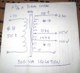
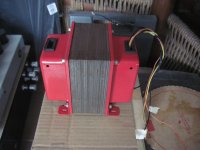
500 VA isolation traffo for my bench top...230 volt primary to 0 to 100, 115, 230 volt secondaries...
Attachments
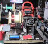

with end bells installed....
An externally hosted image should be here but it was not working when we last tested it.
Attachments
calculate if your chosen wires will fit inside the 1 in x 3 inches winding window...
way i look at it, more like #15 primary and #12 secondary...
i thought that too but first, are my computations possible (power:core) ratio?
secondly the way i look at it as i have samples of number 14 wire
in a window of 1"x3" less the bobbin roughly i would take 7/8 x 2 3/4 allowable winding area, so based on actual #14 magnet wires can turn up to 38 in a 2 3/4 bobbin size. I multiplied 38 x 5 = 190, and 5 turns of #14 occupies about 3/8 of an inch.
next the available window left was 1/2 x 2 3/4 unfortunately i do not have #11 sample but as i look into your table turns per linear inch
enamel D.S.C. or S.C.C. D.C.C
#14 15.0 14.20 13.8 i used 14 turns per linear inch as presumption = it works
#11 10.7 10.3 9.8 i used 9 since i do not have sample to compare with.
the bottom line here are my interpretation and calculations based on your table correct?
thanks
regards
the coil build up is what we look at, if that fits then you can go...
#14 has a diameter of 1.63 mm
#11 has a diameter of 2.3 mm
so how many layers for primary?
how many layers for secondary?
this will guide you to make the final decision...
ok sir thank you for the quick reply
i used english system as i saw it on your table
using metric 25mm x 75mm
#14 actual size at hand was 1.83 into (75mm) 70mm on bobbin 70/1.83 x 5 layers = 191 turns
5 layers x 1.83 = 9.15 or 10mm
for #11 i used the next size guide say for example 2.7mm
#11 @ 2.7mm into a 70mm area will allow 25turns per layer, it needs about 4 layers that will also occupy 10.8mm
that is 9.15 + 10.8 mm = 20mm
by the way i am ordering #11 wire sample to have final measurement.
thank you sir.
20mm is too tight, remember that calculations do not take into account winding factor,
if your calculations give you 20 mm as build up, do not count that that will be the actual buildup once you start winding, that is why i always end up with one size lower, better safe than sorry...
but if you can squeeze them in, why not? use mandrels and a big vise to flatten the coils so it fits...or g-clamps cam be used...
sir tony may i ask if i can get 1500VA on the following toroid?
OD = 8"
ID = 3"
H = 6cm
i do not have a concrete formula on toroid...
thank you
sam
HI, can I help you
Sorry for let response.I am actually not on diyaudio for sometimes
I have some experience in winding toroidal transformer.
As per your toroid core, weight must be over 10kg of that core if the core is M4 Grade silicon steel, you can get maximum 1100VA on that toroid core.for that you need over 5kg copper. I can help you with details.
thank you,
yes sure,.. my pleasure,.. can you give specific details on winding turns for 60-0-60VAC?
but the weight it was mostly about 10 kg.
i can not measure it yet coz im at school.
but i have another toroid core which is intended for higher output that is OD=18cm, ID=9cm, H=12cm approx. 19kg too
im planing to have 65-0-65AC on this toroid and use #13 on primary and #11 on Secondary but no stock of these wires on my supplier so ill wait a little.
please advise
thank you
Cross section calculates to (8"-5")/2 * 2.54 * 6 = 38.1 [cm²]. This basically is what you need to calculate the core's power capability, which should be more than 1100 VA by far.
Best regards!
Dear kay pirinha
Power handling capacity of magnetic cores is affected by the required regulation, copper space, factor and temperature rise limit. The permissible temperature rise depends upon current density, flux density, frequency, class of insulation, duty cycle and the heat dissipation capability of the transformer. That is why power rating cannot be specified precisely.
The power handling capacity
of the magnetic cores may be determined from Eq using the following values
VA=5.0*J*Bm*f*Ac min*ID²*10^-7
where:
VA =Power handling capacity (VA),
J =Current density (A/ mm2),
Bm =Maximum induction ( Tesla),
f =Frequency ( Hz),
ID =Inside diameter (mm),
Ac min =Effective cross-sectional area (mm2).
Now do the math.
thank you,
yes sure,.. my pleasure,.. can you give specific details on winding turns for 60-0-60VAC?
but the weight it was mostly about 10 kg.
I cannot measure it yet coz I'm at school.
but I have another toroid core which is intended for higher output that is OD=18cm, ID=9cm, H=12cm approx. 19kg too
I'm planning to have 65-0-65AC on this toroid and use #13 on primary and #11 on Secondary but no stock of these wires on my supplier so ill wait a little.
please advise
thank you
for 60-0-60Vac (230V/50Hz mains supply) you require
190 turn for primary with 1.63mm dime magnet wire Length (50 Miters)
50 (dual) turn of secondary with 2.34mm dime magnet wire length (26 mitres).
For second core
you can get over 2300VA on that core.
190Turns around the core with a 3" ID will require a large overlap in the winding where it passes through the ID. Roughly 138Turns will fill the ID with ONE layer.for 60-0-60Vac (230V/50Hz mains supply) you require
190 turn for primary with 1.63mm dime magnet wire Length (50 Miters)
50 (dual) turn of secondary with 2.34mm dime magnet wire length (26 mitres).
For second core
you can get over 2300VA on that core.
You will either have to double up the ocassional turn of the primary as you wind on so that the ends of the winding do not overlap,
or just wind on till you use all the ID and then apply a layer, or two of insulation before you add the final 52 turns in the overlap area.
This second alternative puts a high voltage differential between the turns in the overlap region. You don't want just the enamel between wires/turns at near 230Vac differential.
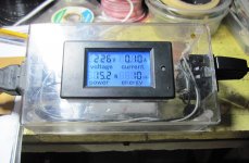
Before you commit to this, try an experiment with around 25% of the turns to check the Turns per Volt needed to get you to not saturated but still high on the "S" curve for good regulation.
Wind on say 50 Turns and use a Variac to determine the Iprimary vs Vprimary. Apply 0Vac to ~65Vac and plot the curve to see the region where Iprimary becomes excessive at high voltage.
Use this to determine the number of Turns you need to the rare occasion when mains voltage is right up at maximum tolerance (254Vac in the UK).
Last edited:
10mm mylar tapes are used for insulation in many commercial toroids,
while some do not even use inter layer insulations...
cotton tapes are also used a lot....
a 190 turn primary for a 230 volt mains is just 1.2 volts, voltage between adjacent turns
the enamel on the magnet wires can withstand way way more than that...
i calculated around 0.9T for the formulas that the "you tube" tutorials use,
assumption is that core quality is that of M6 or better....
commercial toroids out of china may use lower quality,how do we know?
H18 or H50 and we will never know, so it is very important when dismantling burned toroids to get the winding data used and stick with it, operating at say 0.8T (more primary turns) when unsure of core quality...
just below the knee is always the chosen operating point,
but how do you know the knee?
unless the manufacturer of the core gives you that data...
toroids are easier to saturate than a comparable EI,
whether due to dc in the line, or high mains or overloading of the secondary windings....
for 60-0-60Vac (230V/50Hz mains supply) you require
190 turn for primary with 1.63mm dime magnet wire Length (50 Miters)
50 (dual) turn of secondary with 2.34mm dime magnet wire length (26 mitres).
For second core
you can get over 2300VA on that core.
dear sir sanbadgujar,
sorry to confuse you,
that first torroid was already done/made using Primary #16AWG (1.29mm) - for 230V and Secondary #13AWG (1.90mm) for 60-0-60vAC. with mylar tape placed in every layer. "based on my subjective estimation"
but i am grateful you have made a comment and give a good theory atleast next time i can have a better calculations. That was my friend's torroid who asked me some help coz they do not have that patience winding manually.
besides i have also ordered same torroid for my own so your formula does a big help.
that second torroid was mine, and that was what i meant for 1.90mm Primary and 2.34mm Secondary 65-0-65 or if #10AWG, #11AWG are still not available in my supplier. i will use #12AWG 2 x Bifilars
regards
sam
- Home
- Amplifiers
- Power Supplies
- Tony's latest traffo DIY build