sir tony,
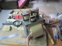
nice looking gears
almost complete,i bet your gear is better than trapo maker @ raon,
it was 2002 the last time i order 20 amp with 65-0-65 big trapo @ richland electronic center by that time it cost me 1,950php.
it was really big and my light flicker every time i power on that amp with that trapo,i already made power on delay for that one.
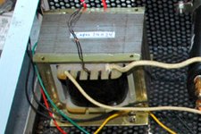
looking at your picture i guess it was a choke coil for a tube amp
nice looking gears
almost complete,i bet your gear is better than trapo maker @ raon,
it was 2002 the last time i order 20 amp with 65-0-65 big trapo @ richland electronic center by that time it cost me 1,950php.
it was really big and my light flicker every time i power on that amp with that trapo,i already made power on delay for that one.
looking at your picture i guess it was a choke coil for a tube amp
Attachments
Attachments
sir tony,
nice looking gears
almost complete,i bet your gear is better than trapo maker @ raon,
it was 2002 the last time i order 20 amp with 65-0-65 big trapo @ richland electronic center by that time it cost me 1,950php.
it was really big and my light flicker every time i power on that amp with that trapo,i already made power on delay for that one.
looking at your picture i guess it was a choke coil for a tube amp
yes, the small ones are choke for tube guitar amps....if you want to roll you own, here is a good place to start: audiofilterchokes
Sir tony, i need help,
i want to rewind this traffo to 0-50 10 amp. can u help me?
the core size is9.6cm H, 8cm W and bobin lenght is5.2cm
sorry for late reply, your traffo is too small for 500watts, you should get a bigger traffo like a 1.75 inches center leg stacked to 3inches....
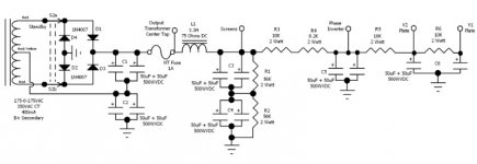
can anybody agree with the
3.3h
75ohm
225mAmp
choke coil for 100w superlead
you can replace that coil with a 75ohm 10watt resistor and you won't even miss the choke....
sir tony i been following this debate
this is from marshal amp forum about this choke
Resistor to choke switch question? - Marshall Amp Forum
Basically what happens is that you have a "ripple" coming from the rectifier circuit, which is basically the positive pulses from the transformer that the rectifier passed through while blocking the negative pulses. These pulses must be filtered into a constant voltage, which is the job of the filter caps.
The first stage filter caps that power the plates of the output valves filter out most of it, but you still have some by the time it gets to the choke. You don't hear it in the output section because 1/2 the output valves are running out of phase from the other half so the 120Hz ripple frequency gets cancelled out of the audio signal. But some of it is still there, which is why you have multiple filter sections in an amplifier.
As the ripple voltage rises positive, it causes a magnetic field to build around the choke coil as the voltage rises. When the voltage falls back toward zero, the magnetic field collapses around the coil and when it does, it induces a counter-voltage into the coil to pick the voltage across the choke coil back up. The voltage across the choke offsets the ripple voltage, thus eliminates some of the ripple.
It also provides a small amount of DC resistance (around 75-110 ohms) between the plate supply and the screen supply.
The "sag" resistor does not provide any filtering at all like a choke does because it is a "non-reactive" component. It does not build and collapse a magnetic field like a choke does. It only provides isolation between the plate and screen to prevent "intermodulation distortion" caused by the plate circuit of the output valves trying to steal current from the screen filter caps. Electrons from the screen filter caps will see the screen as the easier path as compared to having to flow through the sag resistor to get to the plate, and likewise for the electrons supplied by the first stage plate filter caps...they'll see the plate circuit as the easier path rather than the sag resistor and screens.
It is called a "sag" resistor because it is typically a higher value than the DC resistance of a choke. Due to its higher value, it exhibits a higher voltage drop to the proceeding stages more than the voltage drop of a choke as the amp circuitry pulls current through it, which we all know as "voltage sag", or simply "sag".
Advantages to running a choke over a sag resistor is for one, less voltage sag at the screens, phase inverter & preamp as well as more filtering provided by the choke that the sag resistor cannot provide, which will reduce the likelyhood of "ghosting" (i.e. where you hear "ghost harmonics/notes" around the fundamental/original note).
Randy, yes I would recommend switching the amp into Standby mode before making the switch between the sag resistor and the choke.
80+80*20 = 3.2kW
Using the formula VA ~30*(Core area)^2, re-arranged to Core area ~ sqrt(VA/30), you need ~10sqin
That is enormous.
Tony does your method give a similar result?
How does one determine what flux the core can operate at? Steel looks like steel to me.
How does flux affect that formula I quoted?
Finally how does one get from core flux & voltage to primary turns?
Last edited:
^3.2kw is secondary loading....power factor of 0.7 and you need a primary voltampere of 4.27kva
i use the formula from RDH3, VA= (5.58*A)^2;
A= 11.71 square inches,
you need a 2 in center leg x 5.5inch stack of core....
that weighs in at about 19kgs, you need about 3~4kgs of copper...
i use the formula from RDH3, VA= (5.58*A)^2;
A= 11.71 square inches,
you need a 2 in center leg x 5.5inch stack of core....
that weighs in at about 19kgs, you need about 3~4kgs of copper...
Attachments
hi tony
i want to built a transformer for h900 amp. the voltage is 80,40,0,40,80 into 20ampere.
can u give me the bobbin size of the transformer and the ei core size primary and secondary windings wire gauge. so i can search.
my main voltage is 240ac.
thanks.
for a core 2in. center leg stacked to about 5.75inches you will need,
primary, 148 turns #13AWG copper wire,
secondary, 4coils quafillar wound 25turns #12AWG copper
note that i use american standard gauge, i know that in India, the British system is used, so make adjustment to suit your local conditions...
i based my computations on the assumption that you will be using the cheaper non grain oriented steel......
How does one determine what flux the core can operate at? Steel looks like steel to me.
Yes, steel looks like steel, but checking my Waasner catalogue I see already 4 different grades of stamped laminations.
The better the grade, the higher the maximum flux density (and therefore power).
For example: for 3320 secondary VA an EI231b core is required in the best quality (M6-0,35mm). This core has a max flux density of 1,73T.
A lower grade EI231b core has 2700 secondary VA and max T of 1,49, and then there are two even lower grades for this core.
A good grade SE231b double-c-core (this range of c-cores is "equivalent" with EI cores so that the same bobbins can be used) has 3700 secondary VA with 1,75 T, to give you an idea of the higher efficiency of c-cores (one of their pros).
How does flux affect that formula I quoted?Finally how does one get from core flux & voltage to primary turns?
You can calculate flux for a given core and choose the required flux by one of the formulas. I use application sheets of Vacuumschmelze.
When choosing 1 - 1,2 T with a good quality core you will have a "cool" operating transformer with minimal stray fields, also more quiet.
The lower flux requires more primary windings (and therefore winding space) so often a more powerful core is required to get the low flux.
- Home
- Amplifiers
- Power Supplies
- Tony's latest traffo DIY build