Searched around, and couldn't find another thread about this issue. Maybe that's because it's not important, who knows.
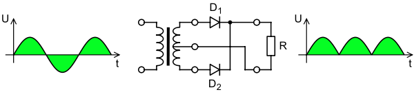
I was doing some breadboarding of a full wave rectifier (two diodes, center-tapped transformer) and resurrected my curiosity about imbalance between the two legs. By measurement, one winding (hot-to-centertap) typically has a higher no load voltage as well as a higher DC resistance. At least with your basic off the shelf transformers.
Result is of course that one hot lead will supply slightly more current than the other hot lead. By superposition, this appears as a perfect full wave rectifier on top of a half wave rectifier. Is this important for a transformer with an air gap, and can it be improved upon?
Simplest method I could think of was to analyze for even order harmonics, prevalent with half wave rectifiers. I went about measuring the primary current on my FFT scope, while playing around with a potentiometer in one of the hot legs of the secondary rectifier. No real change in even order harmonics regardless of the position of the pot. Visually, everything looked equal and balanced on the primary. I assume the gapped core is removing the even order components by balancing the current wave about zero.
Went to the secondary, and simultaneously clamped both secondary hot leads, but reversing the direction of one lead. Now I had a true AC representation of the rectifier output, which if perfect would show no even order. But I did have some. This was confirmed by viewing the waveform, and it was obvious one lead carried more peak current than the other. By adjusting the pot, I could find the happy medium, nulling out even order which was confirmed visually on the waveform.
Old news?
Comments?
Lemme try. Power off, measure DC reistance of winding to either side of center tap. Not even? That means that when you add in the resistive drop in each half winding, you get a small diference. Net result in power suply is a little extra 60Hz ripple on top of the 120Hz. Assuming 60Hz mains. My main suggestion - assuming this matters to you - might be to purchase good quality power transformers. Evenly wound.
purchase good quality power transformers. Evenly wound.
Good luck with that, however. Even the Lundahls, which aren't cheap, have ever so slight differences in either DCR or turns ratio. The point is not to purchase a $400 transformer to resolve the issue when a 50 cent resistor can potentially accomplish the same thing. A full wave bridge will remedy the problem, but off the shelf, center tapped transformers are much more common.
It would be difficult to get equal DCR because of the increasing diameter of the windings makes the length of the wire longer for outer windings, the maker could use heavier gauge wire in the outer winding of the CT.
A resistor would solve the issue and 60 Hz ripple is more troublesome to filter than 120Hz.
The outer secondary winding might also have slightly poorer coupling to the primary which would manifest itself as higher impedance on that winding.
I have a HV transformer which solves this by having a square core and two coils but I run this with a bridge rectifier.
I would have thought that single and split secondary transformers are more common than CT ones. they are in my transformer collection.
Each diode leg went through the current clamp, but with one lead in opposite polarity. Essentially re-creating the AC.
Have you tried this with a smoothing cap on the load? I would expect to see slightly different amplitude charging current pulses. But the differences would probably be smaller than what you see with the pure resistive load. With a cap load the peak currents are higher and a possible higher ac peak voltage will be (partly) compensated by extra drop over the DCR.
At any rate, it appears only to increase the mains freq component in the ripple and not higher harmonics.
jan didden
The actual supply is a choke input filter, 10H and 120uF. The drawing provided is simply taken from a website to illustrate where I am taking the measurements from.
It's not like I stay up at night worrying about equal current draw in my power transformers. This is just an attempt to increase understanding of what happens, and what tools might be available to improve performance. Not everything I investigate requires an emphatic solution. Sure, I could use 2 more diodes and go bridge, but that's not what I am curious about.
From what I have captured on my scope, imbalance does not only increase 60 Hz - the upper even harmonics are increased as well. I'll have to drum up some screen captures.
If the test is valid, it might have some applications in my investigations on a larger scale - power converters or UPS's in the MW range. I would rather investigate on a 100VA transformer rather than one the size of my family room.
That may a manifestation of the difference in coupling between the two halves of the secondary winding and the primary. Industrial scale transformers tend to be more symmetric in their design.
With 3 phase systems any switching time issues in an inverter or phase controlled rectifier show up in the harmonics
- Status
- This old topic is closed. If you want to reopen this topic, contact a moderator using the "Report Post" button.
- Home
- Amplifiers
- Power Supplies
- Random attempt to improve power supply